
How to make a simple (mobile app controlled) DIY Arduino Bluetooth-controlled car with front and back lights with different patterns?
Creating your own Arduino Bluetooth-controlled car with front and back lights is a fun and rewarding project for any electronics enthusiast. This detailed guide will walk you through the step-by-step process of building a custom car that can be controlled via an Android app. By the end, you’ll have a fully functional vehicle featuring various light patterns and four-wheel drive function, all managed by an Arduino UNO R3 microcontroller board and an L293D motor driver module. Whether you’re a beginner or an experienced maker, this project will offer both a challenge and a great learning experience.
Watch Video:
Here is the YouTube video that Explains a more visual way of the Simple DIY Arduino Bluetooth Controlled Car.
Materials Needed:
- Arduino Uno R3 microcontroller board
- L293D motor driver
- HC-05 Bluetooth module
- Cardboard Chassis with four wheels
- Four 100RPM DC motors
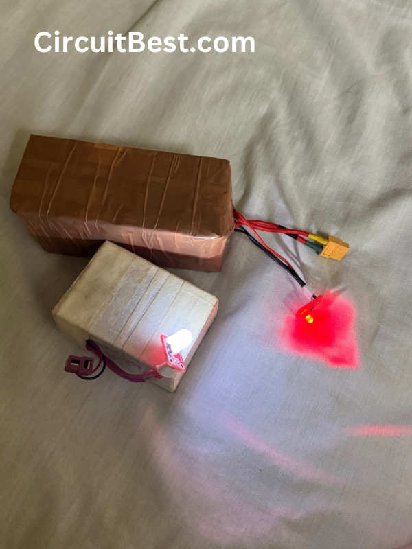
- Two 18650 lithium-ion batteries
- LED lights (front and back)
- 220R Resistors (for current limiting)
- Jumper wires
- Soldering Iron
- Sharp knife
- Android smartphone with Bluetooth capability
Step by Step Instructions to make the car Bluetooth Car:
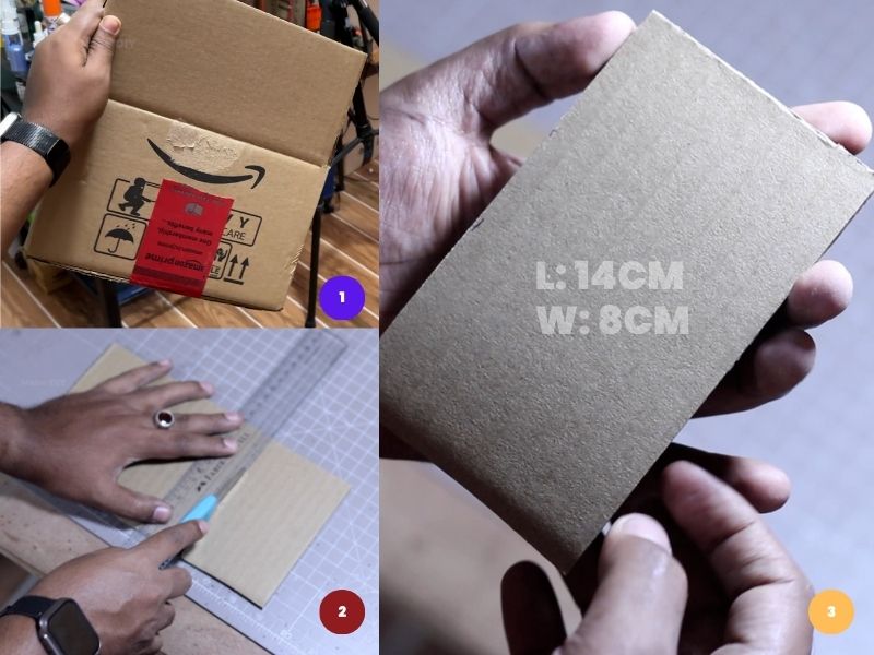
Step 1: Chassis
First, we had to cut the cardboard into the dimensions of the determined shape, 14 CM in length and 8 CM in width. Here I used a Sharp Knife to cut the cardboard.
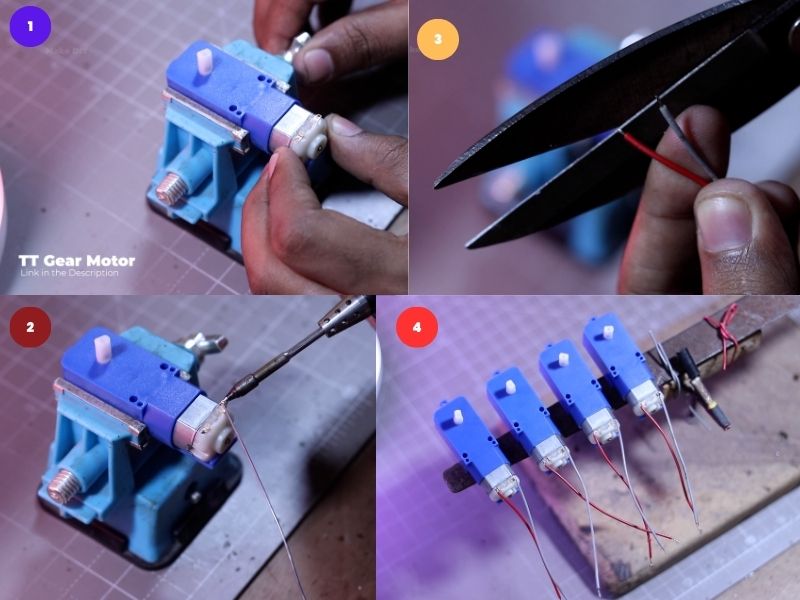
Step 2:
Here I have used TT Gear motor for the 4 Wheel Drive system. Always presolder all the components for better solder joints. Here I pre tinned the wires also for better solder joint.In the same way I have prepared 4 motor with wires.
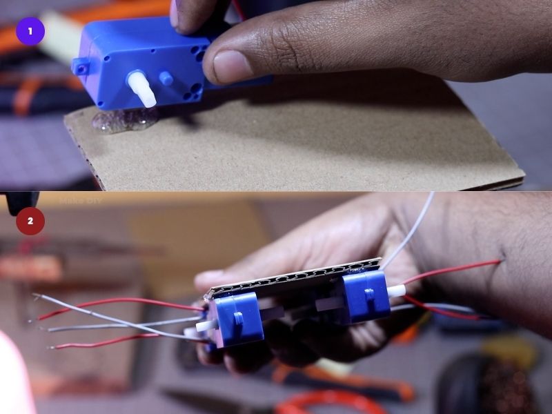
Step 3:
I have used Hot Glue Gun to attach the motors on the cardboard chassis. You can also use Super Glue to attach the motors on the chassis. Make sure that all the motor should have same gravity.
Step 4:
Here we are Using Arduino UNO as the Brain of the car. And it is also one of the best and most popular board for hobbiiests. We will program the Arduino in a way that it will drive the motors as we give the instructions from the Android Phone.
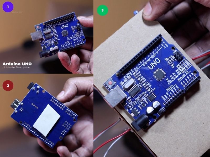
Here I didn’t used the hot glue purposefully. It may break the traces of the Arduino board. So, it is better to use double sided tape with the board.
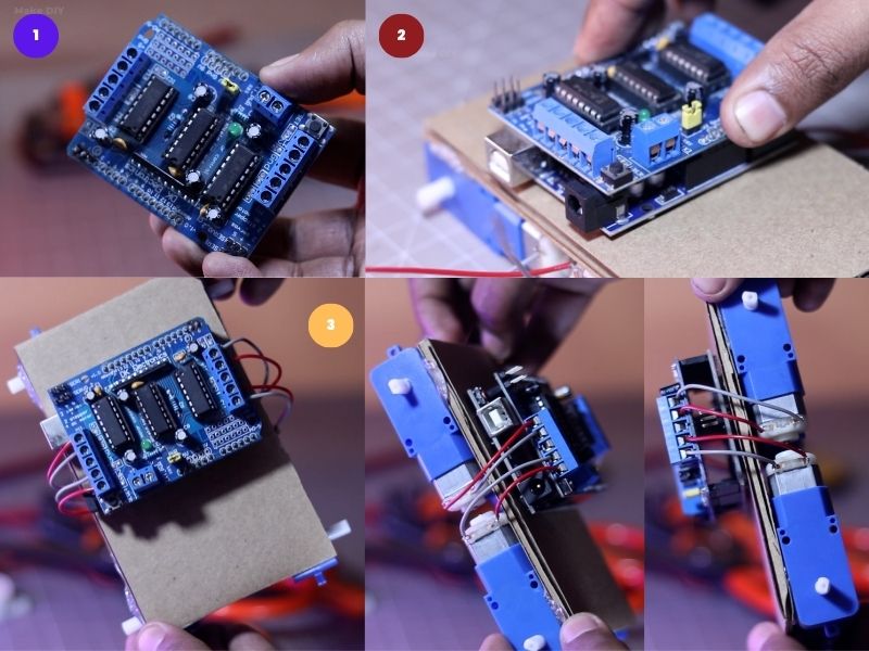
Step 5:
For controlling the motors I have used L293D Motor Driver module to drive the 4WD Car. For using the Motors driver we will need a additional Library (adafruit motor shield). In the code we can give simple BACKWARD, FORWARD command, combined with speed control, we can get all the direction we need for the car.
Step 6:
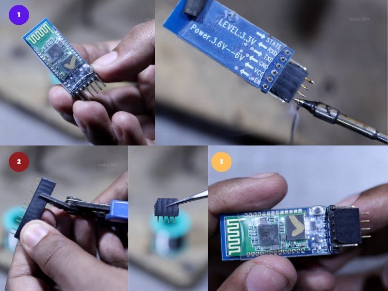
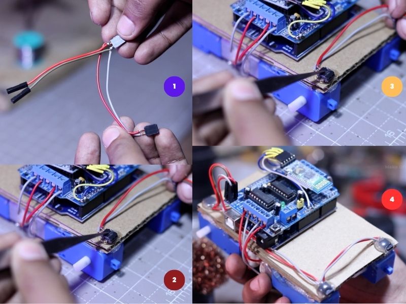
In the Bluetooth Control car project we will need a wireless communication module, since our Arduino don’t have one. We are using Bluetooth as the communication. So, here we are using HC-05 Bluetooth Module.
we can send simple data like F for FORWARD, B for BACKWARD movement of the car. You can check additional directions form the code given at the later step.
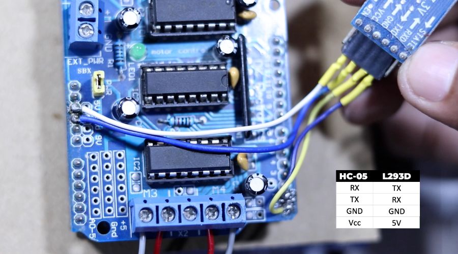
The connection is simple for Arduino to the Bluetooth Module. Vcc to 5v, GND to GND, Rx to Tx, Tx to RX. Here I have used female headers for our convince. Atlast I have used heat shrink tube for better safety.
Note: while uploading the code you have to unplug the connector of the Bluetooth module. Otherwise the code will not upload.
Step 7:
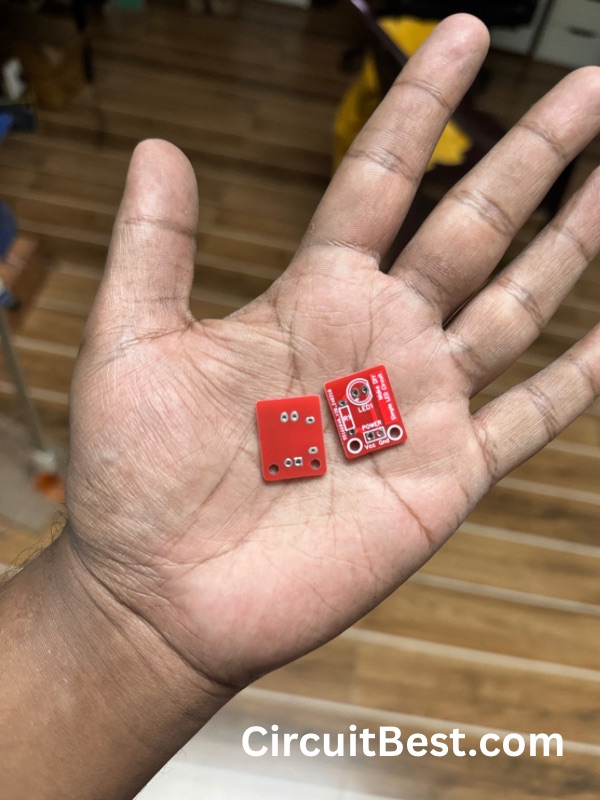
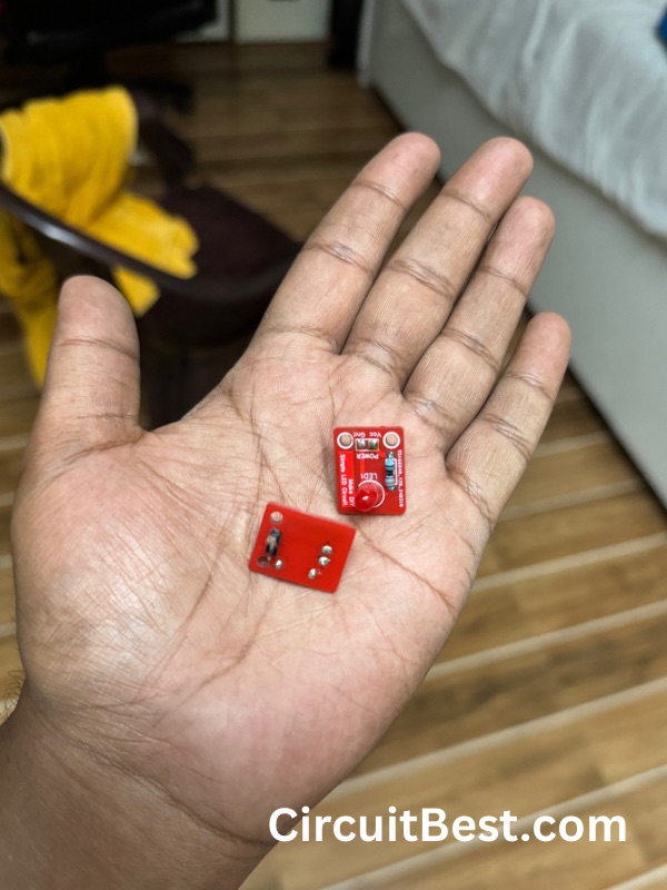
Now it the time to connect the Lights with the car. Here I have made a connector for convince to change the lights colors as your wish. Here if you check the connections carefully then you can see 3 female headers are connected parallely. Specifi
Step 8:
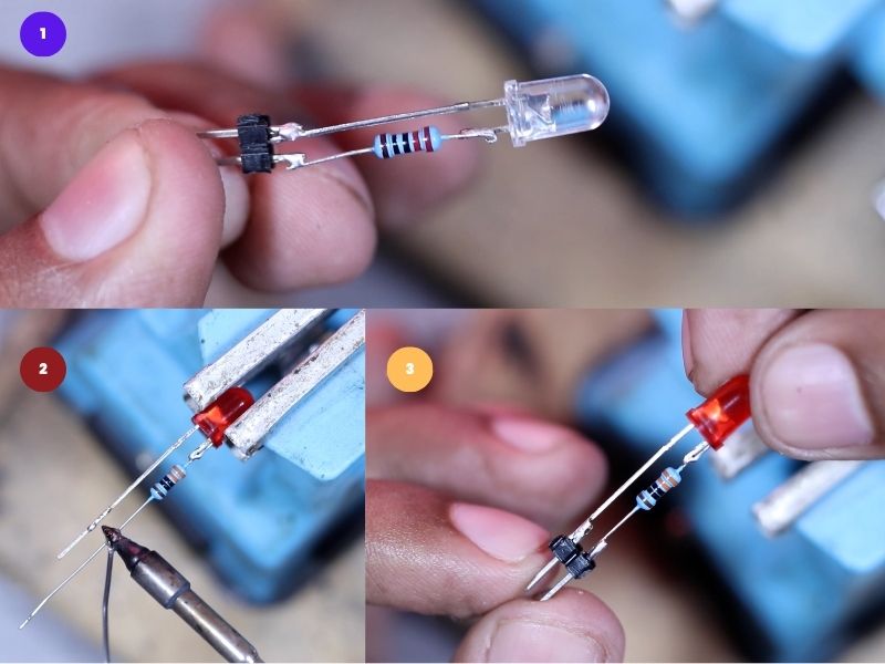
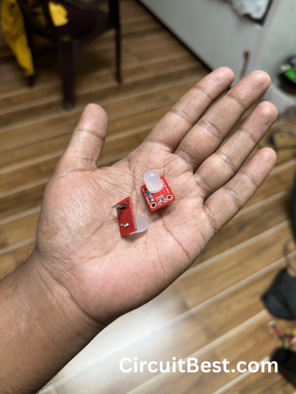
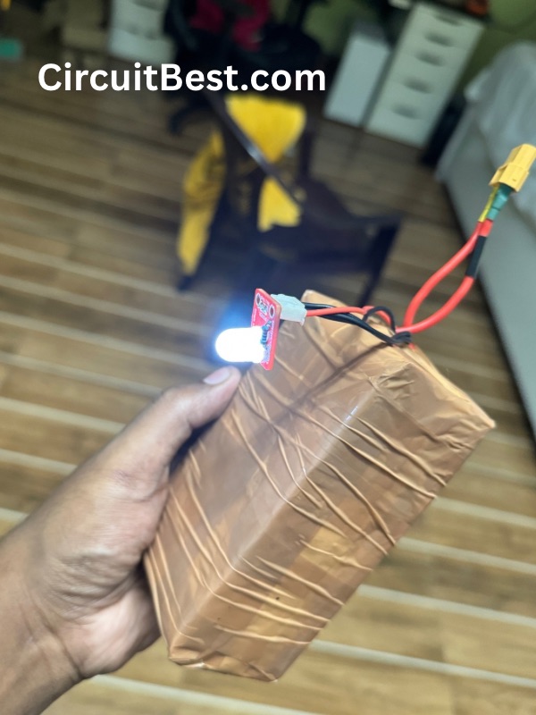
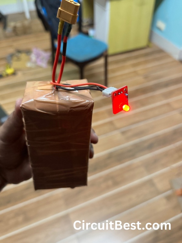
Here for the car we need the front and back lights. For the front lights we are using the 5MM white LED. For the Back lights of the Bluetooth car we are using 5MM RED LED. We are going to use 220R Current limiting resistor for Healthy LED Usage. You can vary the Resistor value 100R to 330R resistor for changing the voltage from 5v to 12V.
Here we are using the male headers for convenience for attachment and removing the LED easily.
Step 9:
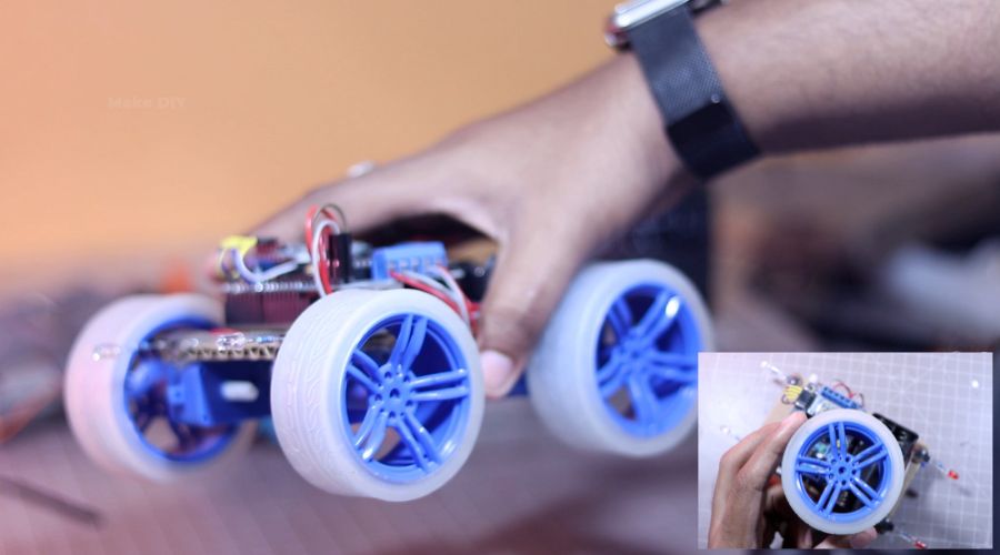
Now we have attached the wheels with the car chassis. Here I used 2″ Blue wheels, you can also use regular yellow Black wheels as well. In the same way I have connected the lights with the car in its corresponding place.
Step 10:
Now it is the time to upload the code to the Arduino Bluetooth Control Car. So I connected the USB B cable to the Arduino. This cable is also known as Printer cable. In one end connect it to the car Arduino UNO R3and in the other end connect it to PC. Now we will upload the code to
At this stage the Car Coding Part is complete, Now we have to install the app to the Android Device. You can download the app from the given link. Allow Unknown Sources to your device as this is a custom made app by me. and I have not added the app to the play store. So, you have to offload the app to your device.
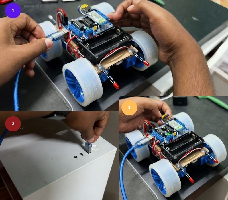
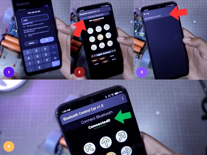
- First Open your Bluetooth settings, search for New device.
- You will see HC-05 Bluetooth Module.
- Then Find it and click on it and connect it.
- After the connection is done then open the app. Then click on the connect Bluetooth Button, and select the HC-05 from the given list.
- You will be able see the changes from RED Not Connected to Green Connected. So, It means the car is connected the the phone.
Step 11:
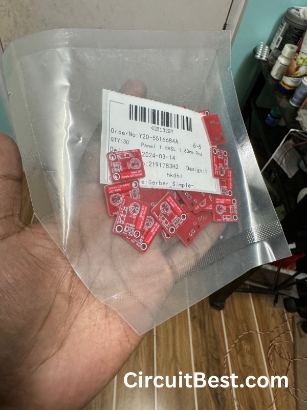
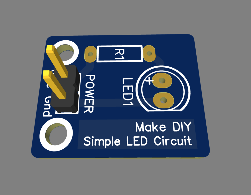
PCB Service:
Here I have used JLC PCB Service for making The Light Modules. Suppose your project needs some serious customization. and your single-layer PCB may not be a great solution for the project. You can even get 1 to 4 layers of PCB for 2$ only.
PCB Order:
- For ordering PCB you will first need a PCB file, which is generally a ZIP file, which you must upload to the website.
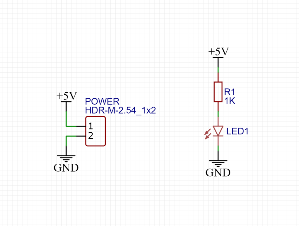
- I designed and created the Schematics in the Easy EDA Software.
- I uploaded the Garber file to the JLC PCB website and made an order.
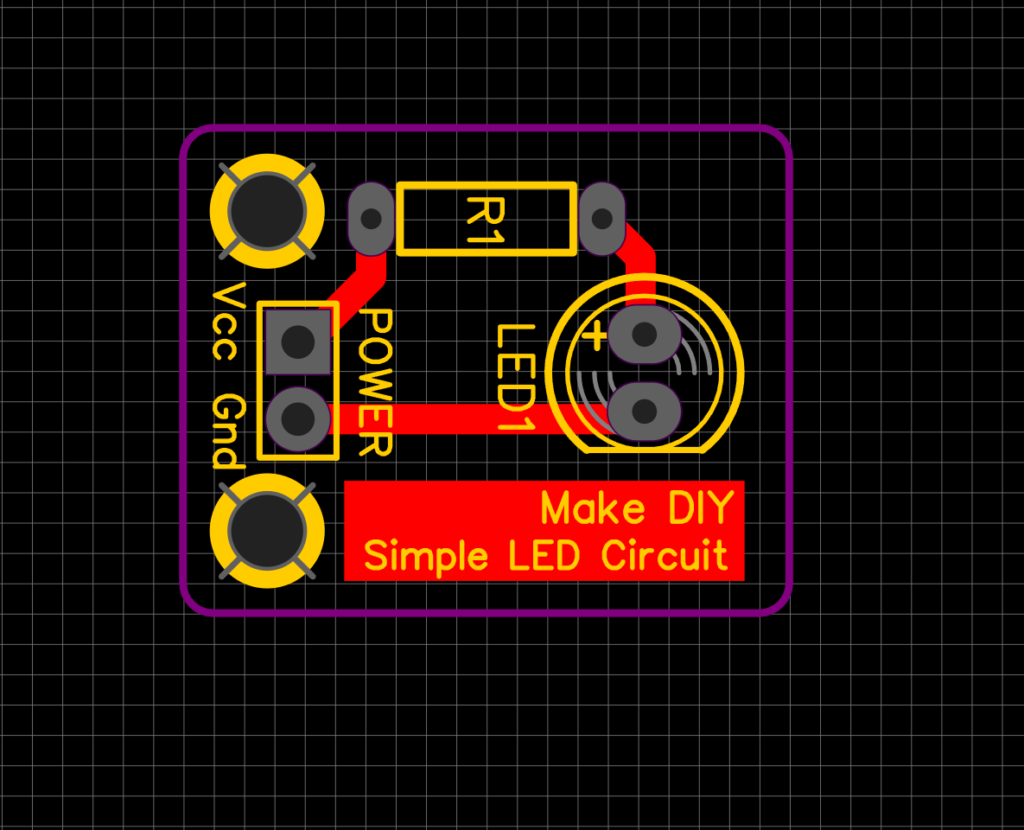
- Once your Garber is checked then the PCB will be put into production.
- These PCBs generally take 1 to 2 days to make. They are really fast at their work.
Right now JlC PCB has some great offers on multi-layer PCBs.

Here are Some Important Links:
I would thank JLCPCB for their kind support for their customers.
Step 12:
Now After uploading the code, the car is ready. Download the BT Car App. Connect Bluetooth from the Android Run the car and Enjoy. If you need any help or need any components for the project you can contact +91 93329 12239.
Code:
/*
Code Name: Arduino Bluetooth Car with Front and Back Light Control
Code URI: https://circuitbest.com/category/arduino-projects/
Before uploading the code you have to install the "Adafruit Motor Shield" library
Open Arduino IDE >> Go to sketch >> Include Libray >> Manage Librays...  >> Search "Adafruit Motor Shield" >> Install the Library
AFMotor Library: https://learn.adafruit.com/adafruit-motor-shield/library-install
Author: Make DIY
Author URI: https://circuitbest.com/author/admin/
Description: This program is used to control a robot using an app that communicates with Arduino through an HC-05 Bluetooth Module.
App URI: https://bit.ly/3mn6LuZ
Version: 1.0
License: Remixing or Changing this Thing is allowed. Commercial use is not allowed.
*/

#include <AFMotor.h>

//initial motors pin
AF_DCMotor motor1(1, MOTOR12_1KHZ);
AF_DCMotor motor2(2, MOTOR12_1KHZ);
AF_DCMotor motor3(3, MOTOR34_1KHZ);
AF_DCMotor motor4(4, MOTOR34_1KHZ);

int val;
int Speeed = 255;
int delay1 = 300;
int LED1 = 9;
int LED2 = 10;


void setup(){
  Serial.begin(9600);  //Set the baud rate to your Bluetooth module.
  pinMode(LED1, OUTPUT);
  pinMode(LED2, OUTPUT);
}
void loop(){
  if(Serial.available() > 0){
    val = Serial.read();

    Stop(); //initialize with motors stoped

          if (val == 'F'){
          forward();
          }
          if (val == 'B'){
          back();
          }
          if (val == 'L'){
          left();
          }
          if (val == 'R'){
          right();
          }
          if (val == 'I'){
          topright();
          }
          if (val == 'J'){
          topleft();
          }
          if (val == 'K'){
          bottomright();
          }
          if (val == 'M'){
          bottomleft();
          }
          if (val == 'A'){
          pattern1();
          pattern1();
          }
          if (val == 'D'){
          pattern2();
          pattern2();
          }
          if (val == 'C'){
          pattern3();
          pattern3();
          }
          if (val == 'X'){
          pattern4();
          }
          if (val == 'Y'){
          pattern5();
          }
          if (val == 'Z'){
          pattern6();
          }
          if (val == 'T'){
          Stop();
          }
  }
}

void forward(){
  motor1.setSpeed(Speeed);
  motor1.run(FORWARD);
  motor2.setSpeed(Speeed);
  motor2.run(BACKWARD);

  motor3.setSpeed(Speeed);
  motor3.run(BACKWARD);
  motor4.setSpeed(Speeed);
  motor4.run(FORWARD);


  digitalWrite(LED1, HIGH);
  digitalWrite(LED2, LOW);
}
void back(){
  motor1.setSpeed(Speeed);
  motor1.run(BACKWARD);
  motor2.setSpeed(Speeed);
  motor2.run(FORWARD);

  motor3.setSpeed(Speeed);
  motor3.run(FORWARD);
  motor4.setSpeed(Speeed);
  motor4.run(BACKWARD);


    digitalWrite(LED2, HIGH);
    digitalWrite(LED1, LOW);
}
void left(){
  motor1.setSpeed(Speeed);
  motor1.run(BACKWARD);
  motor2.setSpeed(Speeed);
  motor2.run(FORWARD);

  motor3.setSpeed(Speeed);
  motor3.run(BACKWARD);
  motor4.setSpeed(Speeed);
  motor4.run(FORWARD);

  digitalWrite(LED1, HIGH);
  digitalWrite(LED2, HIGH);
}
void right(){
  motor1.setSpeed(Speeed);
  motor1.run(FORWARD);
  motor2.setSpeed(Speeed);
  motor2.run(BACKWARD);

  motor3.setSpeed(Speeed);
  motor3.run(FORWARD);
  motor4.setSpeed(Speeed);
  motor4.run(BACKWARD);

  digitalWrite(LED1, HIGH);
  digitalWrite(LED2, HIGH);
}
void topleft(){
  motor1.setSpeed(Speeed);
  motor1.run(FORWARD);
  motor2.setSpeed(Speeed);
  motor2.run(BACKWARD);

  motor3.setSpeed(Speeed/2.4);
  motor3.run(BACKWARD);
  motor4.setSpeed(Speeed/2.4);
  motor4.run(FORWARD);

    digitalWrite(LED1, HIGH);
    digitalWrite(LED2, LOW);
}

void topright(){
  motor1.setSpeed(Speeed/2.4);
  motor1.run(FORWARD);
  motor2.setSpeed(Speeed/2.4);
  motor2.run(BACKWARD);

  motor3.setSpeed(Speeed);
  motor3.run(BACKWARD);
  motor4.setSpeed(Speeed);
  motor4.run(FORWARD);

    digitalWrite(LED1, HIGH);
    digitalWrite(LED2, LOW);
}
void bottomleft(){
  motor1.setSpeed(Speeed);
  motor1.run(BACKWARD);
  motor2.setSpeed(Speeed);
  motor2.run(FORWARD);

  motor3.setSpeed(Speeed/2.4);
  motor3.run(FORWARD);
  motor4.setSpeed(Speeed/2.4);
  motor4.run(BACKWARD);

    digitalWrite(LED2, HIGH);
    digitalWrite(LED1, LOW);

}
void bottomright(){
  motor1.setSpeed(Speeed/2.4);
  motor1.run(BACKWARD);
  motor2.setSpeed(Speeed/2.4);
  motor2.run(FORWARD);

  motor3.setSpeed(Speeed);
  motor3.run(FORWARD);
  motor4.setSpeed(Speeed);
  motor4.run(BACKWARD);

    digitalWrite(LED2, HIGH);
    digitalWrite(LED1, LOW);
}
void Stop(){
  motor1.setSpeed(0); //Define minimum velocity
  motor1.run(RELEASE); //stop the motor when release the button
  motor2.setSpeed(0); //Define minimum velocity
  motor2.run(RELEASE);
  motor3.setSpeed(0); //Define minimum velocity
  motor3.run(RELEASE); //stop the motor when release the button
  motor4.setSpeed(0); //Define minimum velocity
  motor4.run(RELEASE); //stop the motor when release the button

    digitalWrite(LED1, LOW);
    digitalWrite(LED2, LOW);
}


void pattern1(){
    digitalWrite(LED1, HIGH);
    delay(delay1);
    digitalWrite(LED1, LOW);
    delay(delay1);

    digitalWrite(LED2, HIGH);
    delay(delay1);
    digitalWrite(LED2, LOW);
    delay(delay1);
}
void pattern2(){

    digitalWrite(LED1, HIGH); delay(75);
    digitalWrite(LED1, LOW); delay(75);
    digitalWrite(LED2, HIGH); delay(75);
    digitalWrite(LED2, LOW); delay(75);

    digitalWrite(LED1, HIGH); delay(75);
    digitalWrite(LED1, LOW); delay(75);
    digitalWrite(LED2, HIGH); delay(75);
    digitalWrite(LED2, LOW); delay(75);

    digitalWrite(LED1, HIGH); delay(210);
    digitalWrite(LED1, LOW); delay(210);
    digitalWrite(LED2, HIGH); delay(210);
    digitalWrite(LED2, LOW); delay(210);
    digitalWrite(LED1, HIGH); delay(210);
    digitalWrite(LED1, LOW); delay(210);
    digitalWrite(LED2, HIGH); delay(210);
    digitalWrite(LED2, LOW); delay(260);


}
void pattern3(){
   for(int i = 0; i <= 255; i++) {
    analogWrite(LED1, i);
    delay(1);
  }
  for(int i = 255; i >= 0; i--){
    analogWrite(LED1, i);
    delay(1);
  }
   for(int i = 0; i <= 255; i++) {
    analogWrite(LED2, i);
    delay(1);
  }
  for(int i = 255; i >= 0; i--){
    analogWrite(LED2, i);
    delay(1);
  }
}
void pattern4(){

  digitalWrite(LED1, HIGH); delay(75);
  digitalWrite(LED1, LOW); delay(75);
  digitalWrite(LED2, HIGH); delay(75);
  digitalWrite(LED2, LOW); delay(75);

  digitalWrite(LED1, HIGH); delay(75);
  digitalWrite(LED1, LOW); delay(75);
  digitalWrite(LED2, HIGH); delay(75);
  digitalWrite(LED2, LOW); delay(75);

for(int i = 0; i <= 255; i++) {
    analogWrite(LED1, i);
    delay(1);
  }
  for(int i = 255; i >= 0; i--){
    analogWrite(LED1, i);
    delay(1);
  }
   for(int i = 0; i <= 255; i++) {
    analogWrite(LED2, i);
    delay(3);
  }
  for(int i = 255; i >= 0; i--){
    analogWrite(LED2, i);
    delay(3);
  }

}
void pattern5(){
  for(int i = 0; i <= 255; i++) {
    analogWrite(LED1, i);
    analogWrite(LED2, i);
    delay(6);
  }


}
void pattern6(){
    for(int i = 255; i >= 0; i--){
       analogWrite(LED1, i);
       analogWrite(LED2, i);
        delay(9);
    }
}
App:
Conclusion:
Building an Arduino Bluetooth-controlled car is a rewarding and educational project that combines hardware and software skills. By following this step-by-step guide, you can create a fully functional remote-controlled vehicle that can navigate obstacles, display customizable light patterns, and provide hours of entertainment. Whether you’re a beginner or an experienced maker, this project offers a fun and challenging way to explore the world of electronics and robotics.
FAQ: (School/ College Project Requested):
Why HC05 is needed in this Bluetooth control car?
The HC-05 Bluetooth module is essential for enabling wireless communication between the Arduino-based car and the Android app. It allows users to remotely control the car’s movement and light patterns without the need for physical connections.
What are the benefits of four-wheel drive?
The use of four-wheel drive in this Arduino Bluetooth-controlled car project offers several key benefits. Firstly, four-wheel drive provides increased traction and stability, especially when navigating rough or uneven terrain. Each wheel can independently adjust its speed and torque, allowing for better control and maneuverability in various driving conditions.
Secondly, four-wheel drive enhances the car’s ability to climb inclines and overcome obstacles. With power distributed to all four wheels, the car can exert greater force and traction, enabling it to tackle steep slopes and challenging terrain with ease.
Additionally, four-wheel drive improves the car’s overall performance and efficiency. By distributing the workload among four motors, each motor operates at a lower workload compared to a two-wheel drive setup. This reduces strain on individual components and helps prolong the lifespan of the motors and motor driver.
Furthermore, four-wheel drive enhances the car’s versatility and functionality. It allows for a wider range of movements and maneuvers, including turning on the spot and executing precise turns. This versatility is particularly useful for navigating tight spaces or executing complex driving tasks.
Overall, the use of four-wheel drive in this project enhances the car’s performance, stability, and versatility, making it a more capable and efficient vehicle for various applications and environments.
What batteries are used in this project and why it is important?
In this project, two 18650 lithium-ion batteries are used as the power source for the Arduino Bluetooth-controlled car. These batteries are commonly chosen for their compact size, high energy density, and rechargeable nature, making them ideal for portable electronic devices like car.
The use of lithium-ion batteries offers several key advantages for this project. Firstly, they provide sufficient voltage and current to power the motors and electronics of the car, ensuring reliable performance during operation. Additionally, lithium-ion batteries have a relatively long lifespan and can withstand numerous charge-discharge cycles, making them a durable and cost-effective choice for powering the car over the long term.
Moreover, the compact size and lightweight nature of lithium-ion batteries make them well-suited for mobile applications like the Arduino car. They can be easily installed and integrated into the car’s design without adding excessive weight or bulk, ensuring optimal mobility and maneuverability.
Furthermore, lithium-ion batteries offer the convenience of rechargeability, allowing users to easily recharge the batteries when needed using a standard charger. This eliminates the need for frequent battery replacements and reduces the overall cost and environmental impact of the project.
Overall, the use of lithium-ion batteries in this project provides a reliable, efficient, and portable power solution, ensuring optimal performance and usability for the Arduino Bluetooth-controlled car.
How do the lights give different patterns?
The lights in the Arduino Bluetooth-controlled car are programmed to display various patterns using a combination of hardware and software techniques. Firstly, the LEDs used for the front and back lights are connected to the Arduino microcontroller via digital output pins. These pins can be controlled to turn the LEDs on or off, as well as adjust their brightness levels.
To create different patterns, the Arduino code utilizes a series of commands and algorithms to manipulate the LEDs’ behavior. For example, to create a blinking pattern, the code alternates between turning the LEDs on and off at specific intervals. Similarly, to create a fading effect, the code gradually adjusts the brightness of the LEDs over time.
In addition to simple blinking and fading patterns, more complex patterns can also be achieved by combining multiple LEDs and utilizing techniques such as PWM (Pulse Width Modulation). PWM allows the Arduino to control the LEDs’ brightness by rapidly switching them on and off at varying duty cycles. By adjusting the duty cycle, the Arduino can create smooth transitions between different brightness levels, resulting in effects like pulsing, strobing, and color blending.
Furthermore, the Arduino code can incorporate conditional statements and loops to create dynamic patterns that respond to user input or environmental cues. For example, the car’s lights may change patterns based on the car’s speed, direction, or proximity to obstacles.
Overall, by leveraging the capabilities of the Arduino microcontroller and employing creative programming techniques, the lights in the Arduino Bluetooth-controlled car can display a wide range of captivating patterns and effects, enhancing the car’s visual appeal and functionality.
How does the car run in different directions?
- Forward: To move forward, both motors on each side of the chassis rotate in the same direction with equal speed and duty cycle. This propels the car forward in a straight line.
- Backward: To move backward, both motors on each side of the chassis rotate in the opposite direction with equal speed and duty cycle. This causes the car to move backward in a straight line.
- Left Turn: To turn left, the motors on the left side of the chassis rotate forward at full speed (100% duty cycle), while the motors on the right side rotate forward at a reduced speed (less than 100% duty cycle). This creates a torque imbalance, causing the car to turn left.
- Right Turn: To turn right, the motors on the right side of the chassis rotate forward at full speed (100% duty cycle), while the motors on the left side rotate forward at a reduced speed (less than 100% duty cycle). This creates a torque imbalance, causing the car to turn right.
- Forward Left: To move forward and left simultaneously, the right motors rotate forward at full speed (100% duty cycle), while the left motors rotate forward at a reduced speed (less than 100% duty cycle). This causes the car to move forward while turning left.
- Forward Right: To move forward and right simultaneously, the left motors rotate forward at full speed (100% duty cycle), while the right motors rotate forward at a reduced speed (less than 100% duty cycle). This causes the car to move forward while turning right.
By adjusting the speed and duty cycle of the motors on each side of the chassis, you can achieve precise control over the car’s movement in different directions. This differential drive system allows for agile and responsive maneuvering, making the car versatile and adaptable to various driving scenarios.
How the front lights and the backlights are connected?
The front lights and back lights in this Arduino Bluetooth-controlled car project are connected to the Arduino Uno R3 microcontroller via digital output pins. Each LED is connected in series with a current-limiting resistor to ensure safe operation. The positive terminal of each LED is connected to one end of the resistor, and the other end of the resistor is connected to a digital output pin on the Arduino. The negative terminal of each LED is connected directly to ground. This setup allows the Arduino to independently control the brightness and behavior of each LED, enabling the display of various patterns and effects.
How is power supplied to the Arduino Bluetooth-controlled car, and why is it important to use the specified power source?
Power to the Arduino Bluetooth-controlled car is typically supplied by a battery pack or other DC power source. In this project, two 18650 lithium-ion batteries connected in series are commonly used to provide the necessary voltage and current for the car’s operation. It’s important to use the specified power source to ensure reliable performance and safety. The chosen power source should be capable of supplying the required voltage and current to the Arduino, motors, and other components without causing damage or instability. Additionally, using a rechargeable battery pack allows for convenient and portable operation of the car, making it suitable for various indoor and outdoor environments. Properly selecting and configuring the power source is crucial for ensuring the smooth operation and longevity of the Arduino Bluetooth-controlled car.