Introduction:
Hey, what’s up guys today in this article we are going to discuss how we can make a simple street light circuit with some simple transistor resistors and a relay.
And I also want to thank PCBWAY for helping to make this project possible. I will talk more about PCBWAY later but as of now let’s make this circuit.
Schematics of Street light circuit project:
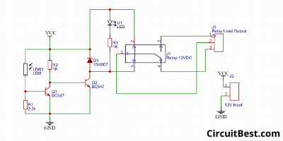
I used online free software easyEDA for making this circuit diagram of the PCB. Let me give you a simple overview of the system. This circuit is based upon cheap NPN transistors. Here I have used LDR as a Light sensor and a Relay as a switch.
The relay is a digital switch that can handle the maximum current. Here we can also use any type of Power Mosfets for making the circuit. I used a Relay for making the circuit simple.
If the external light falls on LDR then the relay should be turned off. And if the LDR is in Dark then the Relay will be on.
How generally the street light circuit project works?
So, Here is the simple Schematics of the circuit. The LDR and the 2.2k resistor makes a voltage divider. At first, suppose that the LDR is not capturing the light. Then the Resistance of the LDR will be close to infinite. So, not current will flow from Q1 NPN Transistor. This time current flows from Vcc to Q2 NPN Transistor’s Base through 1k Resistor. It turns on the Q2 Transistor. The Load that is connected with the Q2 Transistor will be turned on. Here we are using light as a light source So, It became turned on.
In another way, if the LDR Gets light from outside then the Q1 became conductive and all current flows through the shortest path that is VCC to GND 1k Resistor. No current will flow into the Q2 Transistor’s Base. So, Q2 Transistor will not be triggered as well as the Relay.
Related Categories:
Circuit Complexity:
The circuit has so may components so I decided to go with custom PCB. So, I first designed the PCB schematics in the online free software EasyEDA. Then I converted the schematics to PCB from the given option. and ordered it from PCBWAY.COM. Then I checked all the components positions on the PCB with PCBWAY’s Gerber viewer. And that seemed fine to me and I placed my order.
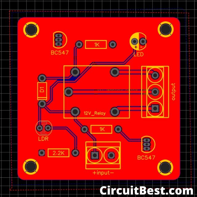
PCB Gerber: Download
Few things about PCBWAY:
They are one of the most experienced PCB manufacturing companies in China. Their customers are from all over the world.
PCB prototyping and manufacturing:
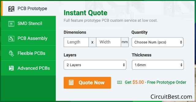
They can not only produce FR-4 and Aluminum boards, but also advanced PCB like Rogers, HDI, Flexible and Rigid-Flex boards, with a very reasonable price. You can make an Online instant quote from here.
There are very punctual with the delivery. They work in three shifts for making sure that their PCBs Top-Notch Quality. They are also providing Quality Production services to their users.
They are providing 2 layers, 4 layers, 6 layer PCBs. Their client support is great and shipping time is also very quick.
2 layer PCB is great for most of the uses. They have a great offer for Hobbyists. They have 100x100mm 10 PCBs for $5 only.
PCB Assembly:
PCBWAY also offers SMT & THT PCB Assembly Services. Their price starts from $30 with a free stencil in all over the world at free of cost. If you want then the components can be provided by them or just you can Source the components by yourself. You can do a rough quote here.
Student Offer:
And wait if you are an Engineering student then you can get a chance for getting free PCB from PCBWAY. They have provided about free PCBs to the 500+ students worth of $25,000.
So if you are a student and if you have any good project then you can tell them about that. Or you can get the Student Sponsorship from Here. They will help you to make your project with the PCB.
More Details:
Here I am providing some more important links from PCBWay. You should definitely check the links given below.
https://www.pcbway.com/why.
https://www.pcbway.com/
https://www.pcbway.com/high-
Steps for making the Circuit:
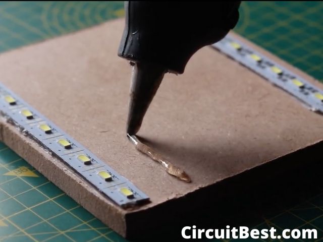
Step 1:
First I placed the LED strips on the MDF board and then attached it with the hot glue. You can also use other wood glue for attaching the LED Strip on the MDF.
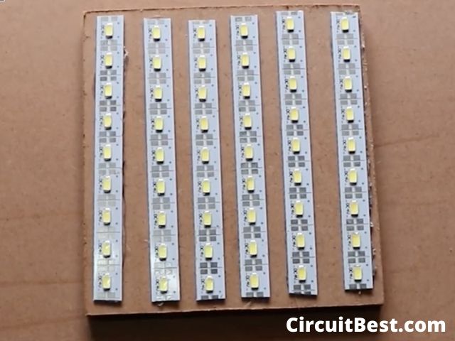
Step 2:
Here I have connected 6 strips. Each LED strip contains 9 LEDs. So, The total will be 54 LEDs on the MDF.
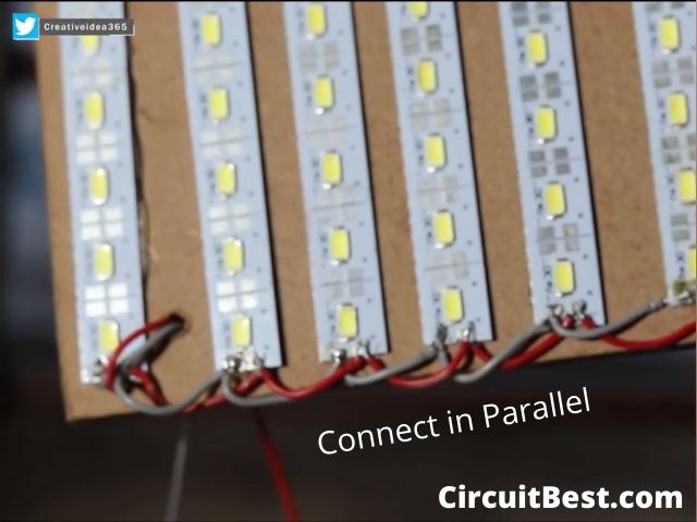
Step 3:
Here I have connected all the LEDs in parallel. Each LED panel is 4v. So, The voltage will be about 4v.
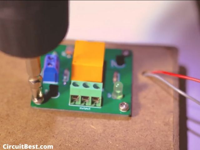
Step 4:
Connected all the components on the PCB. Then I attached the PCB on the backside of the MDF with M3 size screws.
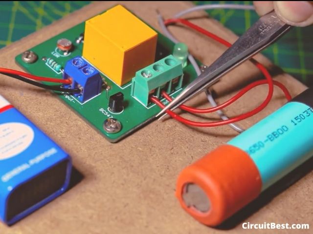
Step 5:
Then I used a 9v Battery for powering the control circuitry. and used a 18650 Battery for powering the main LED. here the relay is used so you can also connect any big loads as well.
Step 6:
After all, things are done I turned off the room light, and here you can see the result. It is working absolutely fine.

The Bottom Line:
So, all in all, I can say PCBWAY is a great company for making prototype PCBs at a very cheap price. If you have a big and complex PCB project then you should definitely try PCBway service at least one time. The street light circuit project is a very easy circuit. you can make it with some simple components which are available in the local market.
You can also read our other article about Arduino LED Chaser Circuit Here.