
Arduino Bluetooth control car using L293D Motor Driver
Today in this article we are going to Make DIY Arduino Bluetooth control car with Arduino UNO R3, L293D Motor Driver, and HC-05 Bluetooth Module. Here you will get Fully Detailed instructions for making Arduino Bluetooth Controlled Car. Codes are also Included.
I have tried to provide you all the must-have Circuit Schematics and Diagrams in this article. My intention was to give you all in one guide for making Bluetooth Car.
If you want to make a School/ College project then this project is for you. You would not need any special knowledge for making the Arduino Bluetooth Robot. So, you should definitely try it.
Watch YouTube Video:
Here is the video from Make DIY YouTube channel. Watch the Full Video and you will understand everything. Next, follow the step by step guide below.
How Arduino Bluetooth Controlled Car Works?
This is a simple Micro-controller based car. The Micro-Controller is connected in the car. The Arduino is doing all this job. For receiving data wirelessly we are using the HC-05 Bluetooth module.
At first, We have to connect/ pair the Bluetooth module with the phone (Android) you want to control. Now, we are doing different operations such as when we press the forward button then the Phone sends a data value to Bluetooth module.
Next, we have to code in a way that if Arduino Gets a Certain Data (Suppose ‘F’ for forwarding) we have to make a certain condition for running the car in a certain direction. So, basically there are many switch cases in the Arduino code. For a known condition or a switch case, the car will perform the added functions in the code.
In the Same way, F, B, L, R are used for moving the car Forward, Backward, Left, Right movement.
Things Needed For Arduino Bluetooth Controlled Car
- TT Motors (Sometimes it is also called BO Motors)
Amazon(US) https://amzn.to/2ZQN85n
Banggood https://www.banggood.in/custlink/KDDEcYDukq - Car Chassis Kit (I used a piece of Plywood for this)
Amazon(US) https://amzn.to/3jxkP3G
Banggood https://www.banggood.in/custlink/G3vRcYGTu5 - Wheels (4 Pieces)
Amazon(US) https://amzn.to/3fRO9jm
Banggood https://www.banggood.in/custlink/G3vECyEGvW - Arduino UNO R3
Amazon(US) https://amzn.to/2WNBt5D
Banggood https://www.banggood.in/custlink/KKDdpYYKm5 - L293D Motor Driver
Amazon(US) https://amzn.to/2OPYmRe
Banggood https://www.banggood.in/custlink/mvmYWddvRW - HC-05 Bluetooth Module
Amazon(US) https://amzn.to/2CYLeXm
Banggood https://www.banggood.in/custlink/vKmDNz2HPz - Jumper Wire (Male-Male, Male-Female, Female-Female)
Amazon(US) https://amzn.to/3eKHDtm
Banggood https://www.banggood.in/custlink/3KDK1VHPY6 - 18650 Battery Holder
Amazon(US) https://amzn.to/32IsGpl
Banggood https://bit.ly/2MkPYrW - 18650 Batteries (2 Pieces)
Amazon(US) https://amzn.to/2OPZNPC
Banggood http://bit.ly/2Ke8xik
Tools Needed for Arduino Bluetooth Controlled Robot
- Soldering Iron
Amazon(US) https://amzn.to/3jtUqUC
Banggood http://bit.ly/2FTWtiN - Solder Wire
Amazon(US) https://amzn.to/39iCveR
Banggood https://www.banggood.in/custlink/KD3Ey07F9l - Solder Paste
Amazon(US) https://amzn.to/3fPDVzS
Banggood https://www.banggood.in/custlink/DKmhE475aE - Glue Gun
Amazon(US) https://amzn.to/2X1Tn4P
Banggood https://www.banggood.in/custlink/KvKYJhRmFH
Popular Categories:
Note: Please Note guys this is the V1 of the car. I will publish a V2 of the car later someday. So, Be a part of the CircuitBest Family.
Schematics of the Bluetooth Control Car with L293D:
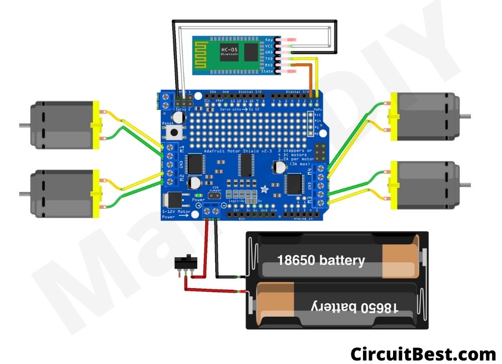
Steps for making the Circuit:
I have divided the Bluetooth control car into several steps. By this, you can understand the Arduino car more easily. Please don’t skip any step otherwise it will be difficult to replicate.
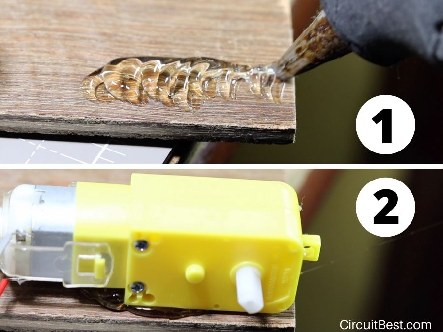
Step 1:
First, you will need 4 TT Motors. Sometimes the motor doesn’t come with wire attached. So, In that case, you have to attach the wire to the motors with a soldering iron.
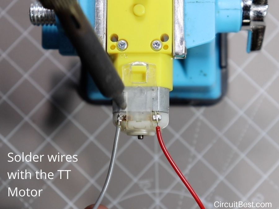
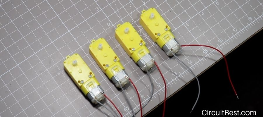
Step 2
In the same way, I have connected wires with Motors. One suggestion to solder is that please don’t heat the motor terminals too much it will be damaged if you heat that too much. After that, I tested all the motors before connecting and it works just fine.
Step 3
Now take a Piece of Plywood dimension of 13CM x 10CM. Now use a Glue Gun and place the motor on the Plywood corners. Use the same technique and connect all 4 Motors on the chassis.
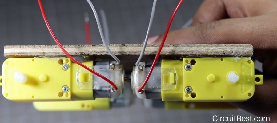
Step 4
I have attached 4 Motor in the Plywood. One suggestion to you is to align the motors. Otherwise, the motors will not go straight.
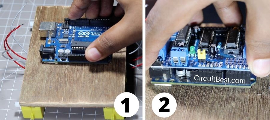
Step 5
First take Arduino Uno and them attach it on the Chassis. Many people use Hot Glue to attach but I don’t recommend that at all. The coper traces under the PCB may be damaged for the hot glue. So, I used Double sided tape for attaching the Board.
For controlling the Motors we will definitely need a motor driver. The L298n and the L293D motor drivers are most commonly used with Arduino. All these drivers have an inbuilt H-Bridge inside in it for controlling the motors.
Step 6
Here is the Left and the Right side view of the Car. You can see the connection more clearly here. If you change the motor wires then the motor rotation will also change. Just connect all the motor as shown in the picture and will work just fine.
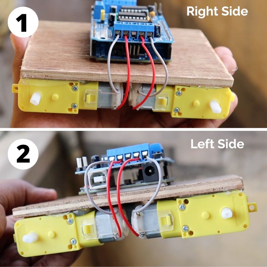
Note: Suppose you are powering a DC motor with a power source like 9V Battery. Just think that your motor is rotating in a certain direction. Now, If you change the connection (Suppose previously you connected Red Wire to the +ve and the Gray wire with the -ve of the battery. So, here changing connection means you have to connect the Red wire with the -ve and Gray wire with the +ve) then the motor will rotate in the opposite direction. This is the property of DC Motor. In this way, you can also check your DC Motor is working or not.
Step 7
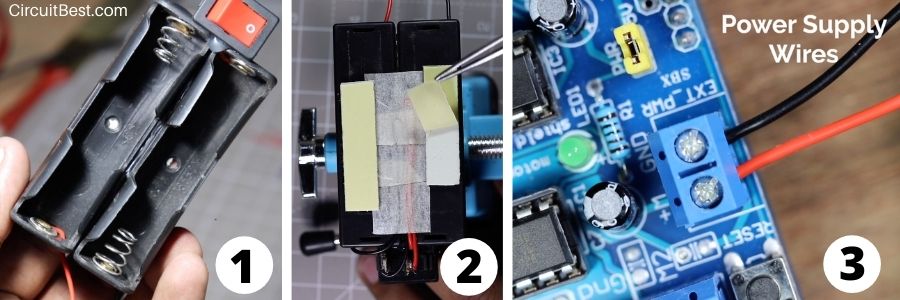
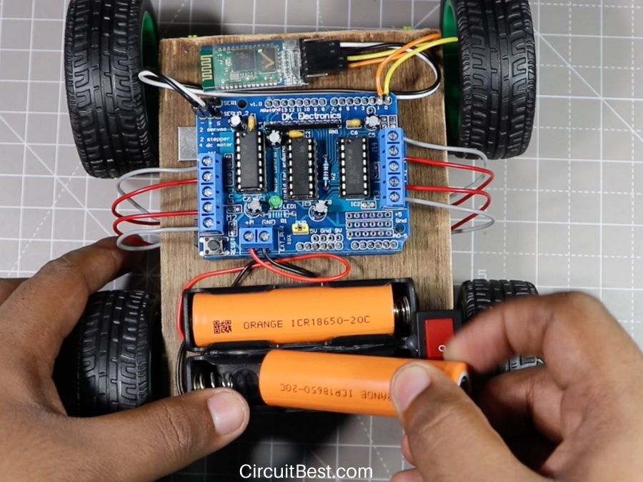
I have used 18650 Batteries for Bluetooth Control Robot. You can also use Li-Po Batteries or Lead Acid Batteries as well. My recommendation is to go with Li-ion or Li-Po Battery because this is most commonly used in DIY Projects. Nowadays you can get 18650 Batteries as cheap as 2$. And these batteries will give you the most power.
Connect the Battery wires with the EXT_PWR Terminal Block. The Battery Terminal block has a Switch inbuilt in it. It is used to turn On/ Off the car. I have attached Double-sided tape with the battery holder and connected with the Chassis.
Note: But one thing I should definitely mention that Li Batteries are great for DIY Projects. But use with care. Charge with Dedicated chargers. Just being at the safe side you may use the TP4056 Li Charger module. And never ever Over-charge, Over-discharge, or short circuit these batteries. It may blast.
Step 8
Now connect the HC-05 Bluetooth Module with the circuit. From the Table, you can see the connections. You will need 2 Female-Female Jumper wires for connecting the 5v(Vcc) and the GND.
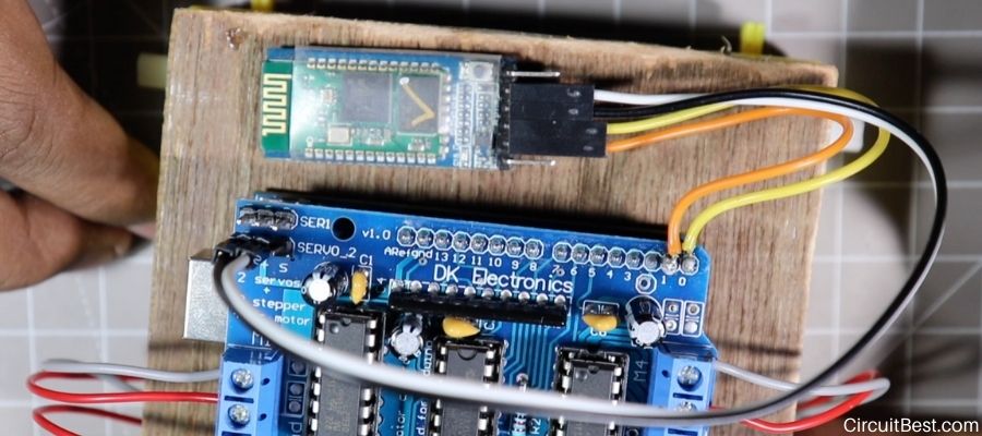
The RX and the TX pins are covered with the Shield. So, we need to solder those pins. Now for connecting the RX and the TX Pins I cut the Male-Female wire and used the female part to connect with the Bluetooth Module. Next I soldered the end wires with the Arduino Pin 0 and Pin 3.
| HC-05 Bluetooth Module | Arduino UNO Board |
| +5v(Vcc) | +Ve (Connected with Servo +Ve 5V) |
| GND | -Ve (Connected with Servo -Ve GND) |
| TX Pin | RX Pin (Digital Pin 0) |
| RX Pin | TX Pin (Digital Pin 1) |
Step 9
Next, connect your Arduino with your PC or MAC. After that, we will dive into the software section.
Step 10
Now, I have provided the code below. Just copy the code and paste it in your Arduino IDE. Before uploading the code to Arduino we need to add a library to Arduino. Just go to the following.
Sketch> Include Library> Manage Libraries…
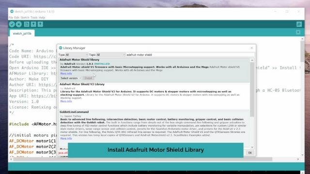
Then Search for Adafruit Motor Shield Library(Adafruit has 2 Libraries for this topic V1 and V2. For our purpose we will only need the V1 library.) from the search bar. Now install the Library. In my case, I have already installed it. So, It is showing already installed.
Arduino Bluetooth Control Car using L293D Code
/*
Code Name: Arduino Bluetooth Control Car
Code URI: https://circuitbest.com/category/arduino-projects/
Before uploading the code you have to install the "Adafruit Motor Shield" library
Open Arduino IDE >> Go to sketch >> Include Libray >> Manage Librays...  >> Search "Adafruit Motor Shield" >> Install the Library
AFMotor Library: https://learn.adafruit.com/adafruit-motor-shield/library-install
Author: Make DIY
Author URI: https://circuitbest.com/author/admin/
Description: This program is used to control a robot using a appthat communicates with Arduino through a HC-05 Bluetooth Module.
App URI: https://bit.ly/2BlMAea
Version: 1.0
License: Remixing or Changing this Thing is allowed. Commercial use is not allowed.
*/

#include <AFMotor.h>

//initial motors pin
AF_DCMotor motor1(1, MOTOR12_1KHZ);
AF_DCMotor motor2(2, MOTOR12_1KHZ);
AF_DCMotor motor3(3, MOTOR34_1KHZ);
AF_DCMotor motor4(4, MOTOR34_1KHZ);

char command;

void setup()
{
  Serial.begin(9600);  //Set the baud rate to your Bluetooth module.
}

void loop(){
  if(Serial.available() > 0){
    command = Serial.read();
    Stop(); //initialize with motors stoped
    //Change pin mode only if new command is different from previous.
    //Serial.println(command);
    switch(command){
    case 'F':
      forward();
      break;
    case 'B':
       back();
      break;
    case 'L':
      left();
      break;
    case 'R':
      right();
      break;
    }
  }
}

void forward()
{
  motor1.setSpeed(255); //Define maximum velocity
  motor1.run(FORWARD); //rotate the motor clockwise
  motor2.setSpeed(255); //Define maximum velocity
  motor2.run(FORWARD); //rotate the motor clockwise
  motor3.setSpeed(255);//Define maximum velocity
  motor3.run(FORWARD); //rotate the motor clockwise
  motor4.setSpeed(255);//Define maximum velocity
  motor4.run(FORWARD); //rotate the motor clockwise
}

void back()
{
  motor1.setSpeed(255); //Define maximum velocity
  motor1.run(BACKWARD); //rotate the motor anti-clockwise
  motor2.setSpeed(255); //Define maximum velocity
  motor2.run(BACKWARD); //rotate the motor anti-clockwise
  motor3.setSpeed(255); //Define maximum velocity
  motor3.run(BACKWARD); //rotate the motor anti-clockwise
  motor4.setSpeed(255); //Define maximum velocity
  motor4.run(BACKWARD); //rotate the motor anti-clockwise
}

void left()
{
  motor1.setSpeed(255); //Define maximum velocity
  motor1.run(BACKWARD); //rotate the motor anti-clockwise
  motor2.setSpeed(255); //Define maximum velocity
  motor2.run(BACKWARD); //rotate the motor anti-clockwise
  motor3.setSpeed(255); //Define maximum velocity
  motor3.run(FORWARD);  //rotate the motor clockwise
  motor4.setSpeed(255); //Define maximum velocity
  motor4.run(FORWARD);  //rotate the motor clockwise
}

void right()
{
  motor1.setSpeed(255); //Define maximum velocity
  motor1.run(FORWARD); //rotate the motor clockwise
  motor2.setSpeed(255); //Define maximum velocity
  motor2.run(FORWARD); //rotate the motor clockwise
  motor3.setSpeed(255); //Define maximum velocity
  motor3.run(BACKWARD); //rotate the motor anti-clockwise
  motor4.setSpeed(255); //Define maximum velocity
  motor4.run(BACKWARD); //rotate the motor anti-clockwise
}

void Stop()
{
  motor1.setSpeed(0); //Define minimum velocity
  motor1.run(RELEASE); //stop the motor when release the button
  motor2.setSpeed(0); //Define minimum velocity
  motor2.run(RELEASE); //rotate the motor clockwise
  motor3.setSpeed(0); //Define minimum velocity
  motor3.run(RELEASE); //stop the motor when release the button
  motor4.setSpeed(0); //Define minimum velocity
  motor4.run(RELEASE); //stop the motor when release the button
}
Now choose the Board as Arduino Uno and Choose the right COM port. Next compile the code first and then Upload the code to Arduino.
Step 11
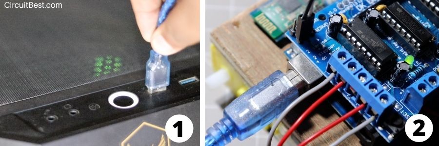
Now I attached the 18650 Batteries in the 18650 Battery Holder. Before powering the car just check all the necessary connections like Battery Power +ve and -ve is connected or not, Bluetooth modules Polarity is right or different. A simple mistake can lead you to damage any modules. And turned on the Switch. Here you will see the L293D Motor Driver’s Green LED as well as the HC-05 Bluetooth Module’s RED LED will glow after turning it on.
Step 12
Now you will need the app for controlling the car. I have given the Application link in the code you can directly download from there and install it to your Android device.
At next open, the application then Click on the small gear button in the app. Then you will find an option called ‘Connect to Car’. After that, you have to select the correct Bluetooth option. For our case, it is HC-05 click on that.
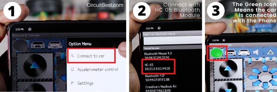
Now you will see that the red Blinking button has changed it’s color from RED to Green. So It means that the car is successfully connected with the phone through Bluetooth. So, the car is finally ready for testing.
Troubleshoot:
- The programmer is not responding: If you face this error then it may be because of the Bluetooth Module. Always Disconnect the RX and the TX pins before uploading the code to the Arduino.
- The motor is not rotating in the right direction: If you face this issue then you don’t need to modify any code. You just have to Interchange the motor wires. In a simple way, I can say just connect the Motor to the Motor driver as I have shown in Step 6.
The Bottom Line:
I hope this step by step guide will help you for making the Arduino Bluetooth control car with L293D whether you are a Beginner or it is your first-ever Arduino project. All components link are included with proper pricing. Hope this helps. If you have any queries or any suggestions then don’t forget to mention that into the comment section. I will definitely try to help you. Moreover, you can subscribe to our Youtube channel Make DIY for more amazing content like this.
You can also read our another article about Arduino WiFi control Car Using NOdeMCU.
Arduino: 1.8.13 (Windows 10), Board: “Arduino Uno”
Error running c:\program files (x86)\arduino\hardware\tools\avr\bin\../lib/gcc/avr/7.3.0/../../../../avr/bin/ar.exe: CreateProcess
exit status 1
Error compiling for board Arduino Uno.
This report would have more information with
“Show verbose output during compilation”
option enabled in File -> Preferences.
why it is showing like this
Arduino: 1.8.15 (Windows Store 1.8.49.0) (Windows 10), Board: “Arduino Uno”
C:\Users\sveera\AppData\Local\Temp\arduino_modified_sketch_5206\sketch_jun07a.ino: In function ‘void Stop()’:
sketch_jun07a:110:22: error: expected ‘}’ at end of input
motor4.run(RELEASE); //stop the motor when release the button
^
exit status 1
expected ‘}’ at end of input
This report would have more information with
“Show verbose output during compilation”
option enabled in File -> Preferences.
compiled but error messages
I’m not sure where you’re getting your info, but great topic.
I needs to spend some time learning more or understanding more.
Thanks for magnificent information I was looking for this information for
my mission.