")
WiFi car Using NodeMCU
In this article, we are going to make an esp8266 smart car. This WiFi remote control car runs with ESP8266 Module also known as NodeMCU. This module is more Powerful than our traditional Arduino UNO Board. It has more memory and also more processing power. The most important thing is that It has Built-in WiFi Module. This small-sized NodeMCU comes with MicroUSB port and also can be operated with 7-12V. You can also program it with Arduino IDE.
What is WiFi Car?
This is a simple car made up of simple components. This WiFi controlled robot runs with the wifi signal. Let me explain in detail.
First, when we connect the whole circuit with the Power Supply, then the NodeMCU creates a server with the given SSID and the Password. Now we have to connect with the Hotspot and have to open the same IP. (i.e. 192.168.4.1) we can give the signal to the Browser address bar but it does not look professional.
ESP8266 Smart Car:
Suppose You want to give the Robot ESP RC to go to the forward command. Then you have to go to the browser address bar and have to type 192.168.4.1/F (We must have to declare F for forwarding in the code.) for WiFi car Using NodeMCU. In the same way, we have to declare all the preferred directions in the esp8266 wifi control code. Now, One by one typing all the IPs is not good in my opinion.
So, Instead of typing every time in the address bar, Here we will use an Android App and from the app, we will give the signals to the microcontroller. With the Instructions, the microcontroller gives data to the motor Driver through the RC ESP connection.
Watch Video:
Here is the video from Make DIY WiFi car Using NodeMCU watch the video till the end and you will get a Rough Idea about the rc car with esp8266.
Components for a Smart car ESP8266 Project:
- Arduino UNO R3: http://bit.ly/2FZY6dT
- TT Gear Motor: https://bit.ly/2Mlb35E
- ESP8266: https://bit.ly/2Ngfvms
- Wheels: https://bit.ly/2U10QPM
- 3s Li-Po Battery: https://bit.ly/3fJcpUh
- HC-05 Bluetooth Module: http://bit.ly/2ukQvod
- 18650 Battery Holder: https://bit.ly/2MkPYrW
- 18650 Battery: https://bit.ly/3eBNH7N
- L298N Motor Driver: https://bit.ly/3gB8Ws6
- Switch: https://bit.ly/3ds4Xfy
- Jumper Wires: https://bit.ly/2MjLy4t
Tools Needed for ESP8266 Car:
- TS1000 Soldering Iron: http://bit.ly/2FTWtiN
- Soldering Wire: https://bit.ly/37MGdwn
- Flux: https://bit.ly/2Yjrczf
ESP8266 Remote Control Car Schematics:
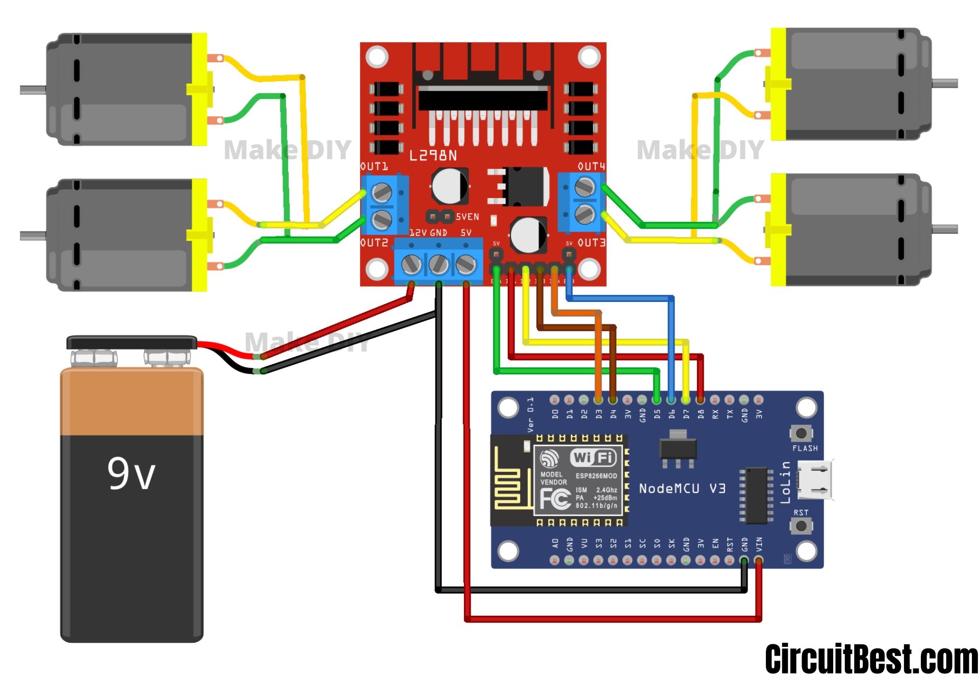
Here is the schematics/ Circuit Diagram of the ESP8266 WiFi Remote Control Car. For the motor driver, I used L298N. This is a high power motor driver capable of running 5V to 35V DC Motor at a maximum of 25W.
We will use 3S, 12V Li-Po Battery so the maximum output per channel will be around 2A. So, It is more than enough to drive this TT Motors.
Simple Steps for making the WiFi Control Car
Step 1
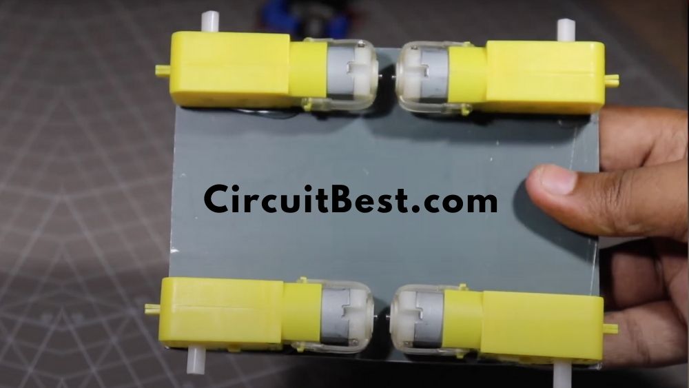
First Cut an MDF or any kind of Board in a Preferred Dimension such as 14CM x 10CM. Make sure that all the edges are cut in equal.

Step 2
Now for the motors, I am using Generic motors i.e. TT Motors. These are very cheap and also great for small projects like this.
Step 3
Now connect 2 opposite sided motors in parallel.
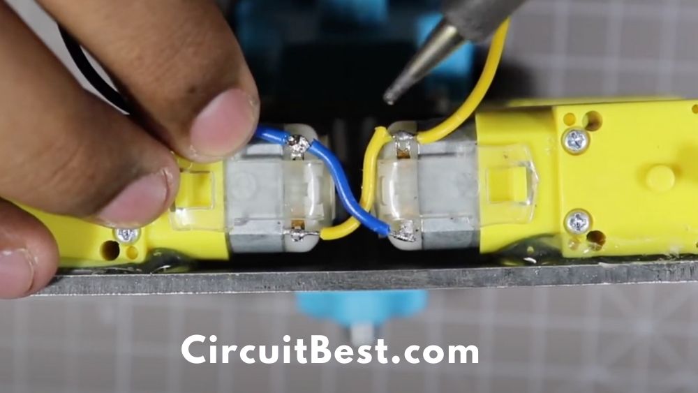
Now when we give them the power to any of the one-sided motors then 2 one-sided motors will work just fine. For testing purposes, I have used 3S Li-po Battery. You can also connect any cheap Battery like a 9V battery for testing.
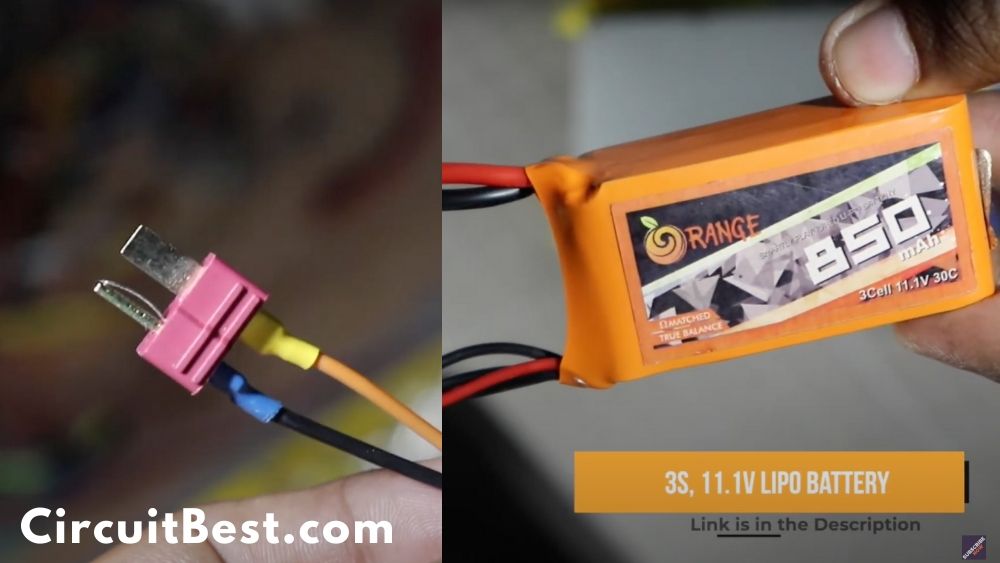
The main reason I avoid 9V batteries this types of projects is that this batteries doesn’t have a good battery capacity. So, gradually it also Drains fast. So, for this reason I just gone with 3S 850 mAh Li-Po Battery.
Step 4
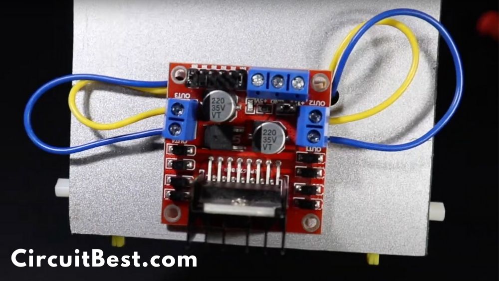
Now for the motor driver, I am using the most popular motor driver L298N. This motor controller can handle high currents such as 35V and a maximum of 35W. So, it is suitable for my work. You can also use the L293D Motor Driver. In that case, the code will be different. We will also cover that thing for my future articles.
You can also read our another Article
Step 5
Now connect the motor wires with the motor driver. You can connect the motor wires in any direction. At the Troubleshooting section, I am going to discuss more in detail. For now, just connect the wires with the motor driver.
Step 6
For giving the power to the modules I am using 3S Li-po Battery. This battery connector this uses is T-connector. Many of the newer batteries uses XT60 connector. You can use both of then as your wish. And if your budget limits you then you can also go with 9v Battery and its Clip. It will also just work fine for WiFi car Using NodeMCU.
Connect the Battery +Ve wire with the +12v and connect the -Ve wire with the GND wire. For the 9V battery, you have to do the same +Ve to the +12v and the -Ve to the GND.
Step 7
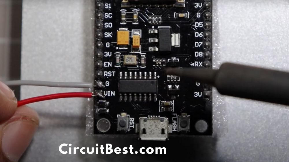
For the wifi module I am using NodeMCU ESP8266 Module. This module has a WiFi module inbuilt in it. So, we don’t need to buy rather more WiFi stuffs.
This WiFi module creates a hotspot. We have to connect the Hotspot through any of our device and have to give the command to the module. Suppose we want to run the car in forwarding so in the coding section, we have declared that if we get “F” data then it will run the car in forward.
In the same way, we have to declare all the things. where we want to move the car. We can add Car Head Light, Backlight, Buzzer as a Horn, and much more. More about that later. It is a topic for another article. For now, Let’s continue our next Step.
Step 8
Now we have to give the power to the ESP Board. ESP8266 needs 5v. so for the 5v we are using Motor Driver’s 5v output.
Step 9
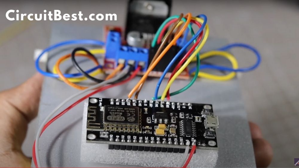
Now we gave to make a communication line between the ESP and the Motor Driver Module. Here are the connected pins diagram for the connection.
| ESP8266 | L298N Motor Driver |
| D3 | Input 4 |
| D4 | Input 3 |
| D5 | Enable A |
| D6 | Enable B |
| D7 | Input 2 |
| D8 | Input 1 |
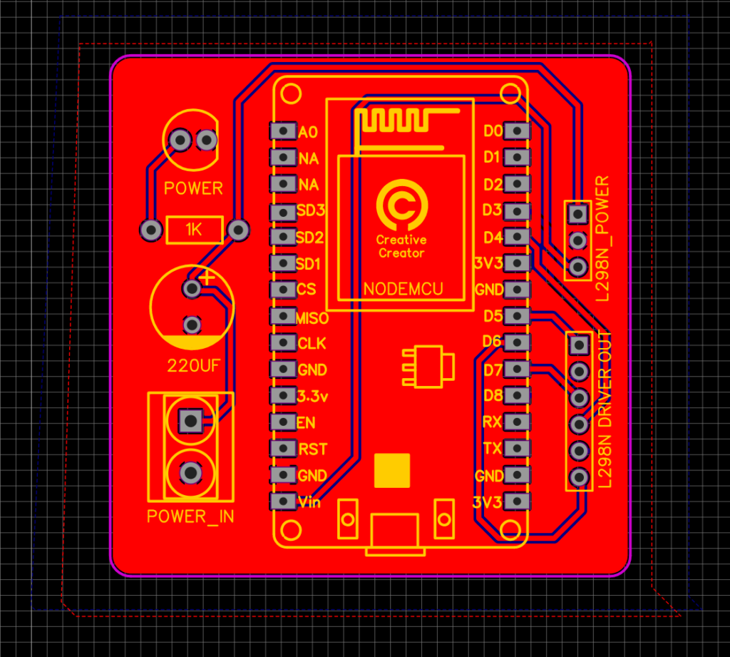
Simplified PCB:
Here is the simplified PCB for the NodeMCU Car. If you don’t want any wire mess and want to make a clean car that runs great then you can consider these schematics. You can order PCB from PCBWay. They are very professional in their work.
The schematics contains all the necessary parts that are also needed for the normal build and also other complementary parts that will make the finished product more realistic look. Here I have used a 220UF capacitor for smoothing and also for giving the car maximum power when the Gear Motors are in serious load.
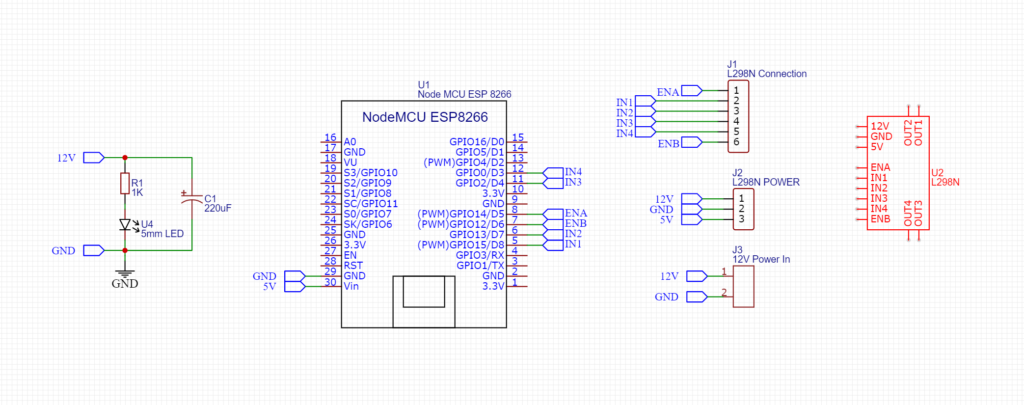
Here I added a LED couple with a 1K resistor for the Power Indicator. I have used 2 pin screw terminal block for giving power to the PCB.
There are some Breakout points for connecting the car to the L298N Motor Driver Module. So, In this scenario, there is no wire mess. So go to our sponsor PCBWAY.com for ordering PCB.
PCB Layers:
I have used EasyEDA for making the circuit schematics. The PCB size is 50MM x 50MM. So, it is a pretty small and compact. This is a 2 Layer PCB Red is the top layer and the Blue is the bottom layer.
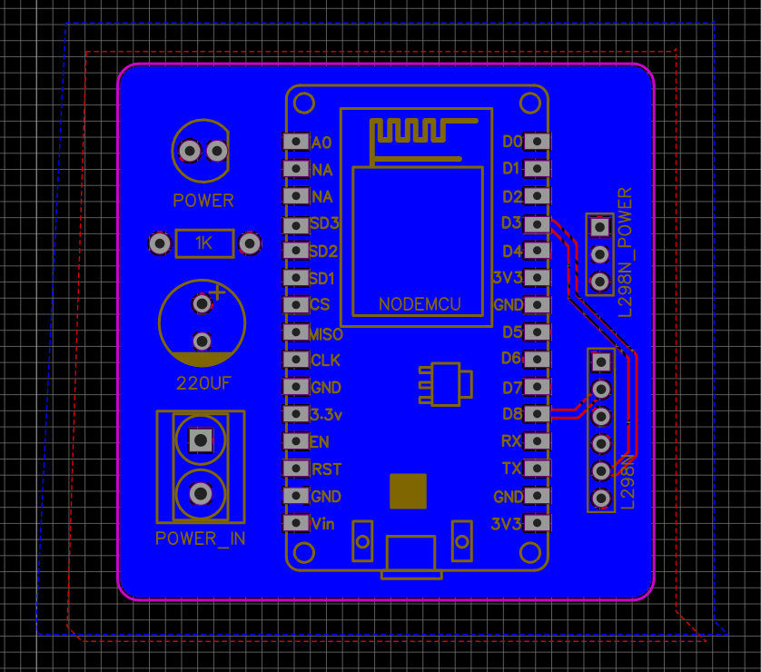
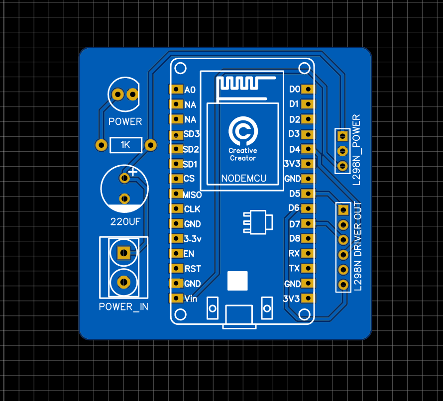
PCB View:
These are the 2D and 3D views of the PCB. This is only for reference purposes. the original product may differ at some point. But I can assure you that if you have the knowledge and if you want to make something circuit related then you can easily do that with the help of PCBWay.
Order PCB:
For the PCB production, I have chosen the PCBWay website. They are one of the largest PCB manufacturers in china. Just Upload your Gerber files today and get your first 10 PCBs only for 5 dollars. The processing time is fast and the shipping time is also very quick and you can see the PCB Quality in the video. Those are great.
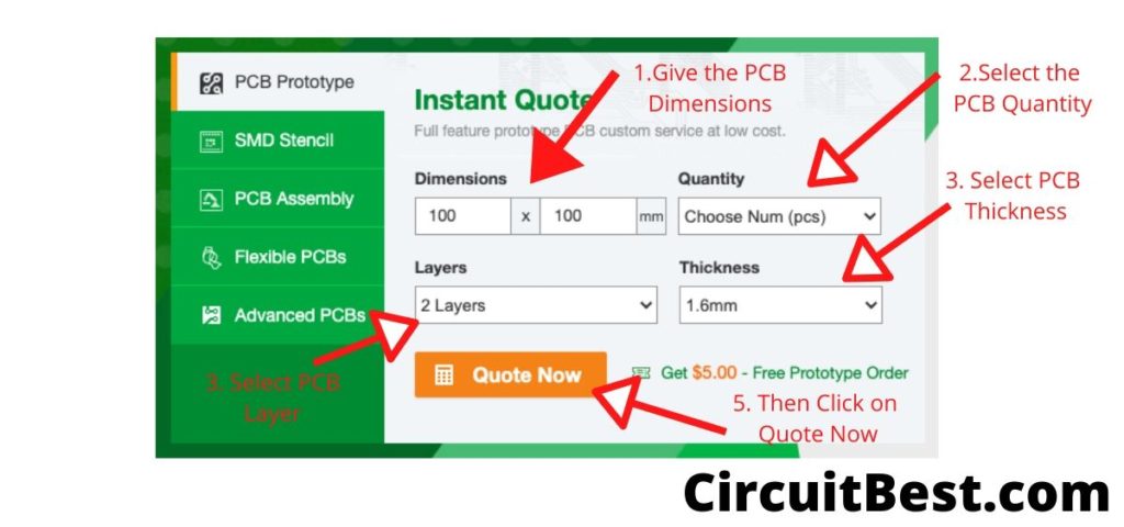
Go to PCBWAY.com and then click on Instant Quote. Now here are the basic settings for publishing a post.
- First, Give the PCB Dimensions. PCBway has great deals on 100mm x 100mm PCBs.
- Select the Number of PCBs you want to order.
- For prototype PCBs, you can order 5 Samples and upwards.
- Choose 2 Layer PCB.
- General PCB thickness is 1.6mm which is ok for hobby projects.
- Click on the Quote Now.
Submitting PCB Design to PCBWAY
Here is the typical PCB Submitting Page. You will find all types of PCB customizations here. Like Board Type, Size, Layer, Thickness, and much more.
- PCBWAY supports multilayer PCBs such as 14 Layers PCBs also.
- Now you just need to upload the PCB. PCBWAY will take care of all the certain parameters of the PCB.
- After that, it comes to the payment part. In this case, you can use any credit card, Debit Card, or PAYPAL. They have 128 bit SSL encryption on their server.
- Within a week you will receive your PCB and use it for the Arduino Line follower car.
PCB Gerber Link: Download
Step 10
Now connect a USB Cable with the ESP8266 and the PC and then I will Jump into the software section. First install Arduino IDE in your PC or Mac. Here I will discuss how all the things should be done with any OS you prefer.
- First Download the code from the link below. Now open Arduino and Go to File>New.
- Now a new window will appear. Next, Delete all the existing code and Paste the given code.
- In the code, you will find Additional Board Manager URL now copy the URL and do the next step. For Different OS you have a different option.
- MAC: Go to Arduino > Preferences
- Windows: Fille > Preferences
- Now Paste it in the Additional Board Manager URL section and press Ok.
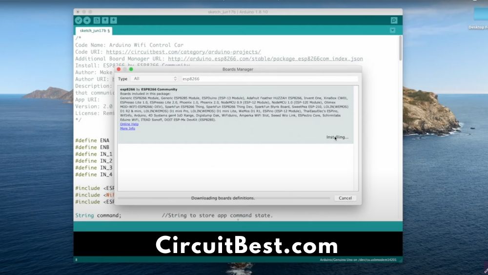
- Now go to Tools > Board > Boards Manager
- Search for ‘ESP8266‘ and install the latest version.
- After the installation Then go to Tools > Board and then select the ESP-12E Module. So, The Board is selected Now.
- Next, Select the Right COM Port.
- Then compile the Programme First and then Upload to NodeMCU. After a few seconds, the code will be compiled and then Uploaded to NodeMCU Car.
Additional Board Manager URL: http://arduino.esp8266.com/stable/package_esp8266com_index.json
Step 11
- Connect the Car with the battery.
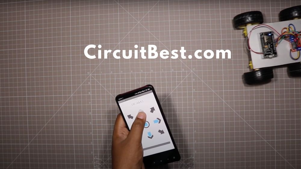
- Now Install the Application link below.
- Connect with the WiFi. In the general case, you will find the Wifi SSID is ‘Make DIY’. You can change the wifi Name by changing the SSID.
- Now open the app and you will be able to control the car with the app.
- The car also has a speed slider by which you can control the speed of the WiFi car Using NodeMCU.
Troubleshoot:
Here I am defining some general troubleshoot of the car.
Not Moving Right Direction:
- Suppose you are pressing the forward button but the car is going to the back or it is rotating to the clockwise or anticlockwise direction. Then you have to do a simple step.
- Just face your car to the forward direction and then press the forward button.
- Next check which wheel is rotating which side.
- If it is rotating in the wrong direction then change motor wires. And your problem will be solved.
**I will add more Troubleshoot for WiFi car Using NodeMCU if I get more.
NodeMCU WiFi controlled Car Code:
/*
Code Name: Arduino Wifi Control Car
Code URI: https://circuitbest.com/category/arduino-projects/
Additional Board Manager URL: http://arduino.esp8266.com/stable/package_esp8266com_index.json
Install: ESP8266 by ESP8266 Community
Author: Make DIY
Author URI: https://circuitbest.com/author/admin/
Description: This program is used to control a robot using a app
that communicates with Arduino through a ESP8266 Module.
App URI: https://drive.google.com/file/d/1pvtWsTeXhcJdpHMfGlFmbGDuH7eoLfoP/view?usp=sharing
Version: 2.0
License: Remixing or Changing this Thing is allowed. Commercial use is not allowed.
*/


#define ENA   14          // Enable/speed motors Right        GPIO14(D5)
#define ENB   12          // Enable/speed motors Left         GPIO12(D6)
#define IN_1  15          // L298N in1 motors Rightx          GPIO15(D8)
#define IN_2  13          // L298N in2 motors Right           GPIO13(D7)
#define IN_3  2           // L298N in3 motors Left            GPIO2(D4)
#define IN_4  0           // L298N in4 motors Left            GPIO0(D3)

#include <ESP8266WiFi.h>
#include <WiFiClient.h>
#include <ESP8266WebServer.h>

String command;             //String to store app command state.
int speedCar = 800;         // 400 - 1023.
int speed_Coeff = 3;

const char* ssid = "Make DIY";
ESP8266WebServer server(80);

void setup() {

 pinMode(ENA, OUTPUT);
 pinMode(ENB, OUTPUT);
 pinMode(IN_1, OUTPUT);
 pinMode(IN_2, OUTPUT);
 pinMode(IN_3, OUTPUT);
 pinMode(IN_4, OUTPUT);

  Serial.begin(115200);

// Connecting WiFi

  WiFi.mode(WIFI_AP);
  WiFi.softAP(ssid);

  IPAddress myIP = WiFi.softAPIP();
  Serial.print("AP IP address: ");
  Serial.println(myIP);

 // Starting WEB-server
     server.on ( "/", HTTP_handleRoot );
     server.onNotFound ( HTTP_handleRoot );
     server.begin();
}

void goAhead(){

      digitalWrite(IN_1, LOW);
      digitalWrite(IN_2, HIGH);
      analogWrite(ENA, speedCar);

      digitalWrite(IN_3, LOW);
      digitalWrite(IN_4, HIGH);
      analogWrite(ENB, speedCar);
  }

void goBack(){

      digitalWrite(IN_1, HIGH);
      digitalWrite(IN_2, LOW);
      analogWrite(ENA, speedCar);

      digitalWrite(IN_3, HIGH);
      digitalWrite(IN_4, LOW);
      analogWrite(ENB, speedCar);
  }

void goRight(){

      digitalWrite(IN_1, HIGH);
      digitalWrite(IN_2, LOW);
      analogWrite(ENA, speedCar);

      digitalWrite(IN_3, LOW);
      digitalWrite(IN_4, HIGH);
      analogWrite(ENB, speedCar);
  }

void goLeft(){

      digitalWrite(IN_1, LOW);
      digitalWrite(IN_2, HIGH);
      analogWrite(ENA, speedCar);

      digitalWrite(IN_3, HIGH);
      digitalWrite(IN_4, LOW);
      analogWrite(ENB, speedCar);
  }

void goAheadRight(){

      digitalWrite(IN_1, LOW);
      digitalWrite(IN_2, HIGH);
      analogWrite(ENA, speedCar/speed_Coeff);

      digitalWrite(IN_3, LOW);
      digitalWrite(IN_4, HIGH);
      analogWrite(ENB, speedCar);
   }

void goAheadLeft(){

      digitalWrite(IN_1, LOW);
      digitalWrite(IN_2, HIGH);
      analogWrite(ENA, speedCar);

      digitalWrite(IN_3, LOW);
      digitalWrite(IN_4, HIGH);
      analogWrite(ENB, speedCar/speed_Coeff);
  }

void goBackRight(){

      digitalWrite(IN_1, HIGH);
      digitalWrite(IN_2, LOW);
      analogWrite(ENA, speedCar/speed_Coeff);

      digitalWrite(IN_3, HIGH);
      digitalWrite(IN_4, LOW);
      analogWrite(ENB, speedCar);
  }

void goBackLeft(){

      digitalWrite(IN_1, HIGH);
      digitalWrite(IN_2, LOW);
      analogWrite(ENA, speedCar);

      digitalWrite(IN_3, HIGH);
      digitalWrite(IN_4, LOW);
      analogWrite(ENB, speedCar/speed_Coeff);
  }

void stopRobot(){

      digitalWrite(IN_1, LOW);
      digitalWrite(IN_2, LOW);
      analogWrite(ENA, speedCar);

      digitalWrite(IN_3, LOW);
      digitalWrite(IN_4, LOW);
      analogWrite(ENB, speedCar);
 }

void loop() {
    server.handleClient();

      command = server.arg("State");
      if (command == "F") goAhead();
      else if (command == "B") goBack();
      else if (command == "L") goLeft();
      else if (command == "R") goRight();
      else if (command == "I") goAheadRight();
      else if (command == "G") goAheadLeft();
      else if (command == "J") goBackRight();
      else if (command == "H") goBackLeft();
      else if (command == "0") speedCar = 400;
      else if (command == "1") speedCar = 470;
      else if (command == "2") speedCar = 540;
      else if (command == "3") speedCar = 610;
      else if (command == "4") speedCar = 680;
      else if (command == "5") speedCar = 750;
      else if (command == "6") speedCar = 820;
      else if (command == "7") speedCar = 890;
      else if (command == "8") speedCar = 960;
      else if (command == "9") speedCar = 1023;
      else if (command == "S") stopRobot();
}

void HTTP_handleRoot(void) {

if( server.hasArg("State") ){
       Serial.println(server.arg("State"));
  }
  server.send ( 200, "text/html", "" );
  delay(1);
}
App Link: Download
You Can also Read our other Article About Android Controlled RGB LED Strip Using Arduino
Sir the nodemcu is getting the signal but not moving the motors
how do i edit the code and the app and add light and button?
i got the same think happen with my car
whoah this blog is great i really like reading your posts.
Stay up the good work! You understand, lots of individuals are looking round for this info, you can aid them greatly.
This is very interesting, You’re a very skilled blogger.
I have joined your feed and look forward to seeking more of your
excellent post. Also, I have shared your web site in my social networks!