
Introduction:
LEDs are Great for Lighting. Controlling the brightness of the LED strip is quite a difficult task with Bare hands. In this project, we are going to make an Android App Controlled RGB LED Strip. This Circuit is for Demonstration Purposes. I have used JLC PCB Service for this Project. The Heart of this project is Arduino Nano. and for Driving the LEDs I used 3, IRFZ44N Mosfets.
For the components section, I have gone with UTSOURCE. They are one of the largest component suppliers in China. They offer different types of components such as Resistors, Capacitors, ICs and many other things. You will get exclusive discounts for Today in this article we are going to discuss shown to makes a simple Long Distance Transmission System circuit. So, let me give you a brief description of the circuit. So, why you are waiting for? Place your first order from UTSOURCE.
0 Profit selling KN95 masks and Infrared Thermometer from UTSOURCE.net: https://www.utsource.net/home/healthcare
Components needed:
- Arduino Nano: https://www.utsource.net/itm/p/9221680.html
- HC-05 Bluetooth: https://www.utsource.net/itm/p/7566177.html
- Resistors: https://www.utsource.net/itm/p/8328095.html
- Capacitor: https://www.utsource.net/itm/p/1872752.html
- Screw Terminal Block: https://www.utsource.net/itm/p/612970.html
- 5MM Green LED: https://www.utsource.net/itm/p/9942990.html
- Wires: https://www.utsource.net/itm/p/9221308.html
- BC547 Transistor: https://www.utsource.net/itm/p/6964442.html
Tools Needed:
- Soldering Iron: https://www.utsource.net/itm/p/8423764.html
- Iron Stand: https://www.utsource.net/itm/p/7722853.html
- Nose Pliers: https://www.utsource.net/itm/p/7671655.html
- Flux: https://www.utsource.net/itm/p/8423764.html
Watch the YouTube Video about Android Controlled RGB LED Strip Using Arduino:
Here is the video from Creative Creator Watch this Step by Step Without any skip and you will understand everything.
RGB LED Strip:
This LED Strip mainly made up of SMD LEDs. If you give a specific voltage then the LED lights up. We can’t able to control the LED strips with the Data signal. So, it means that all LED strip Colors will remain Constant. To run the LED strips you will need Constant 12V Power source. For the Pinouts, It has 4 pin output. 1, +ve and 3 GNDs. The 3 GND points are for 3 individual Colors. They are for Red, Green, and Blue. In 90% of cases, the Internal Connections are the Same. 3 LEDs connected in series and 1 Resistance in Parallel. The Resistance is for Limiting the Current. This same internal Circuit is Present in every circuit. Now there are Many Branches Like this and all of these Brunches connected in Parallel. (Polarity takes the vital role.)
Schematics Of Android Controlled RGB LED Strip:
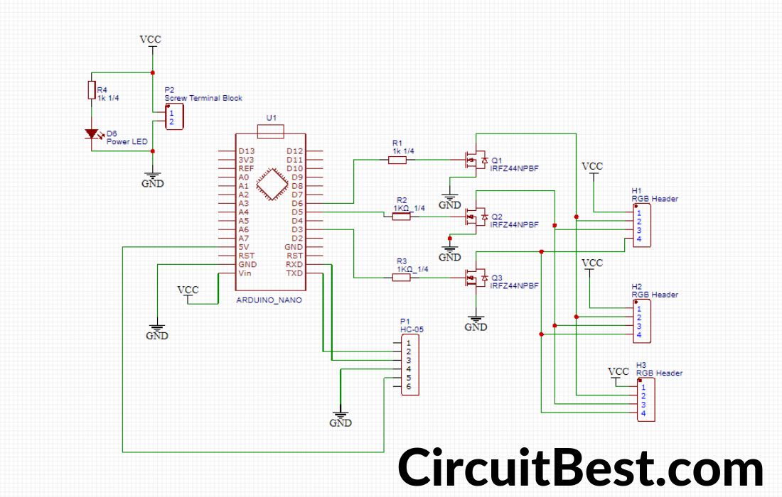
How the RGB LED Strip Controller Circuit Works?
You will need an Arduino for Providing the PWM pulses to the LED. These PWM Pulses are not strong enough for running the LED Strips. At next, we will need some Power Transistors for running the LED strips.
For the Power Transistor Selection, I have gone with IRFZ44N N-Channel Mosfet. Use The Mosfet can Drive 3 or 4 LED Strips with Ease.
In the LED strip There are 3 Individual LEDs there are Red, Green, and Blue. I will use 3 Mosfets for this Project. Every LED is Connected with Each Mosfet.
Let’s Take Mosfet a, b, c. a is for Red. b is for Green and c is for Blue. Now Suppose we want to light up the Red LED from the LED Strip. So, what we need to do is to Give the PWM Pulses to the Gate pin Of Mosfet a. Similar cases will have Appeared for the Other Colors.
In Coding Language we say ‘0’ for LOW and ‘255’ for HIGH. Let me give you some examples of how it is written. suppose you want to light up the Green LED., in this case, the RED LED will be off as similarly, Blue LED will be off. The syntax will be (RED_VALUE, GREEN_VALUE, BLUE_VALUE). For this, it will be (0, 255, 0).
For Controlling the LED Strip we are using an Android App. This App is connected over Bluetooth. and Sends Data to Arduino NANO. The Arduino NANO reads the data and Sends the RGB data to the LEDs by PWM Pulses. In this way, the LED strip gives Different colors.
Steps for making the Circuit:
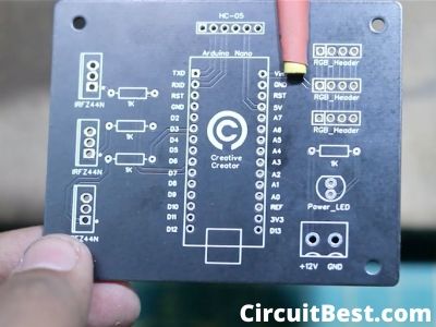
Step 1:
First I examined the PCB. and checked whether or not the PCB internal connection is ok or not. After testing with a multimeter I find that the internal connection is fully functional and working perfectly.
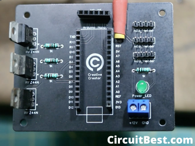
Step 2:
Then I gathered all the components which are needed for the PCB. At next I connected all the components to its position.
Step 3:
then I connected the USB cable with the Laptop and the Arduino nano. One thing you should note that here I am using an Arduino nano with old BootLoader. So you should select the old Bootloader Version.

Step 4:
After the coding part, I have connected the 4 Pin LED wire with the circuit Male Headers. And also I have connected the Bluetooth Module with the circuit.
 Step 5:
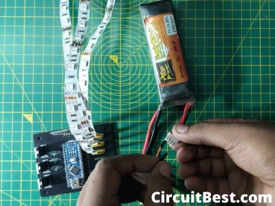
For the Power Supply, I have used a 3s 12v Li-Po Battery with the circuit. You can also use any 12V Power supply in the circuit.
 Step 6:
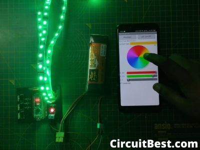
Now I opened my Bluetooth and searched for the HC-05 Bluetooth Module. Generally, the password for the Bluetooth module is 0000 or 1234. I have downloaded the app from Play Store. Selected the right Bluetooth button and connected it. And Here you can see the LED color is changing with my finger swipe. So now RGB LED Strip using Arduino controlled is working.
Download Links:
Android Controlled RGB LED Strip Using Arduino Code:
#include <SoftwareSerial.h>

SoftwareSerial BLU(0,1);

#define redPin 5
#define greenPin 6
#define bluePin 3

void setup()
{
  //Serial setup
  Serial.begin(9600);
  Serial.println("-= HC-05 Bluetooth RGB LED =-");
  BLU.begin(9600);
  BLU.println("-= HC-05 Bluetooth RGB LED =-");

  pinMode(redPin, OUTPUT);
  pinMode(greenPin, OUTPUT);
  pinMode(bluePin, OUTPUT);

  setColor(255, 0, 0);
  delay(500);
  setColor(0, 255, 0);
  delay(500);
  setColor(0, 0, 255);
  delay(500);
  setColor(255, 255, 255);
}

void loop()
{
  while (BLU.available() > 0)
  {
    int redInt = BLU.parseInt();
    int greenInt = BLU.parseInt();
    int blueInt = BLU.parseInt();

    redInt = constrain(redInt, 0, 255);
    greenInt = constrain(greenInt, 0, 255);
    blueInt = constrain(blueInt, 0, 255);

    if (BLU.available() > 0)
    {
      setColor(redInt, greenInt, blueInt);

      Serial.print("Red: ");
      Serial.print(redInt);
      Serial.print(" Green: ");
      Serial.print(greenInt);
      Serial.print(" Blue: ");
      Serial.print(blueInt);
      Serial.println();

      BLU.flush();
    }
  }
}

void setColor(int red, int green, int blue)
{
  analogWrite(redPin, red);
  analogWrite(greenPin, green);
  analogWrite(bluePin, blue);
}
Notes:
- The app is made from App Inventor. As a result, it is not optimized for Android devices. Some times the app Crashes too much.
- Use 12V Powersupply for the Circuit.
- The Arduino Nano’s Voltage regulator gives 5v to run the Arduino. for this, you can use 9 to 12v any.
You can also Read Our Another Article about LED Chaser Circuit With Arduino.