This Simple circuit represents How you can make an Optocoupler with LED and LDR. This is not fully an optocoupler but the working concept is the same. For an Optocoupler, there is an infrared LED and A transistor. There is no physical connection between both parts. The Light part emits the light and the transistor’s base catches the light and it became conductive so that it flows the current from its collector to the emitter. So, basically, the switch became close. so it floes the current.
In my circuit, the Main concept is simple
- There is no Physical connection between LED and the LDR
- So, the Primary and the secondary sides are isolated.
- The safety of the optocoupler is working perfectly here
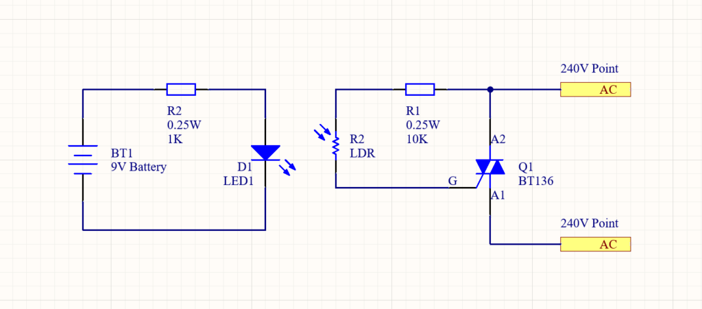
In my circuit when I give power to the LED then the Light falls on the LDR. then the resistance of the LDR gets a lower value so it flows current from directly AC to the Triac’s Base. So, the Triac became conductive and it flows current from A2 to A1. So, the Load that is connected through the Triac will be powered up.
YouTube Video:
Schematics/ Circuit Diagram of Simple Optocoupler representation with BT136 Triac: