
LED Dimmer Circuit with 555 Timer:
Simple & Easy LED Dimmer Circuit Using 555 IC for LED Strip Lights. I will show you how to make a dimmer circuit for LED Strips, Lights with 555 timer IC. This LED Dimmer Circuit is based on 555 timers. We are using 555 timers for generating a PWM pulse. Then the PWM pulses drive an N channel power MOSFET. Here we are using MOSFET for the LED dimmer circuit so you can run high ampere LEDs. Here I am using IRFZ44N n channel MOSFET if you want to make this project you can use another MOSFET also make sure you have read all the datasheets.
Needed Components for LED Dimmer Circuit:
- IRFZ44N: https://www.utsource.net/itm/p/9223667.html
- LED: https://www.utsource.net/itm/p/6831354.html
- Resistor: https://www.utsource.net/itm/p/8328095.html
- Capacitor: https://www.utsource.net/itm/p/1898386.html
Tools Needed:
- Soldering Iron: https://www.utsource.net/itm/p/8423764.html
- Iron Stand: https://www.utsource.net/itm/p/7722853.html
- Nose Pliers: https://www.utsource.net/itm/p/7671655.html
- Flux: https://www.utsource.net/itm/p/8423764.html
Watch YouTube Video:
Schematic of the LED Dimmer Circuit:
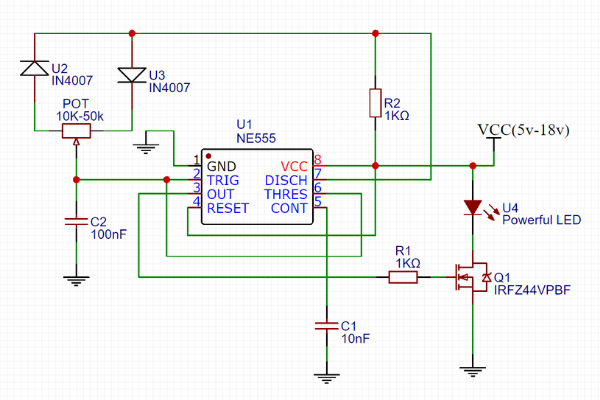
Here is the Non-Contact AC Voltage Detector Circuit Diagram Made with Online Free Easyeda Software.
How does the LED Dimmer Circuit work?
This circuit is based on 555 timers. We are using 555 timers for generating a PWM pulse. Then the PWM pulses drive an N channel power MOSFET.
Of course, you need some complementary components for 555 timers to suggest resistors, capacitors, potentiometers.
The potentiometer is used for increasing or decreasing the duty cycles of the PWM signal.
You are 100% duty cycle means full brightness and 50% duty cycle means half brightness 0% means the light will be off.
Here we are using MOSFET for the LED dimmer circuit so you can run high ampere LEDs.
Hair the circuit basically works for 12v appliance but you can the circuit with higher loads also. In that case, the ground point will be the same but the positive voltage will be greater such as 24Volts.
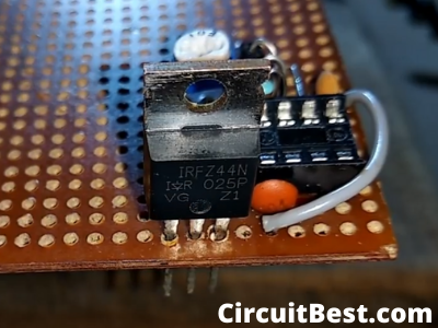
Here I am using IRFZ44N n channel MOSFET if you want to make this project you can use another MOSFET also make sure you have read all the datasheets.
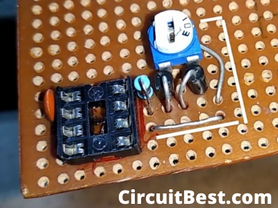
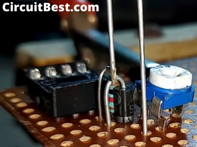
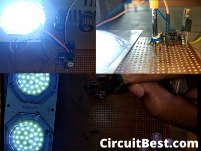
Steps for Making the Circuit:
Here are Some Pictures for making the Circuit. I have made the LED Dimmer Circuit in the PCB for making the circuit as simple as possible. You can also make the circuit in the Breadboard. But there may be loose connection So I have Directly Soldered all Components. So, there will not be any loose connection.
Here are some Detailed Pictures of the Circuit which I have made on the Printed Circuit Board. I have connected a 12V LED with the circuit and connected it with 12v Power Supply.
Note:
- You should use a fine bit of the soldering iron. It will be easier to solder on the breadboard.
- Use a heat shrinking tube for or securing the necessary connections.
- The flyback diode is not necessary for the LED dimmer circuit. But if you are making the motor speed controller then you should use the flyback diode it will protect the transistor from the motor back EMF.
You can also read another article about Non-Contact AC Voltage Detector Circuit