

AC Line Tester:
AC Voltage Detector Circuit is a simple circuit based NPN transistors like BC747, BC548. the circuit based on 3 different stages. after that the weak signal became strong and This circuit is able to run the LED as well as the buzzer. Here is a quick article with a Video tutorial for this Project. This can also be done with CD4017 Decode counter But for an easier solution, The transistor Method is best.
Things Needed for the Audio Amplifier:
- LED: https://www.utsource.net/itm/p/6831354.html
- Resistor: https://www.utsource.net/itm/p/8328095.html
- Capacitor: https://www.utsource.net/itm/p/1898386.html
- BC547: https://www.utsource.net/itm/p/9223667.html
Tools Needed:
- Soldering Iron: https://www.utsource.net/itm/p/8423764.html
- Iron Stand: https://www.utsource.net/itm/p/7722853.html
- Nose Pliers: https://www.utsource.net/itm/p/7671655.html
- Flux: https://www.utsource.net/itm/p/8423764.html
YouTube video link:
Here is our YouTube channel’s video. You can also watch the video for better understanding. Feel free to subscribe to our YouTube channel and don’t forget to press the bell icon.
Circuit Schematics:

Here is the Non-Contact AC Voltage Detector Circuit Diagram Made with Online Free Easyeda Software.
How the Circuit Works?
AC Voltage Detector Circuit is based on simple transistors basics. This is a Basic Amplification Process. The Base Pin of the transistor_3(T3) is used for sensing the ac signal oscillation.
At the first time, the AC detector circuit is not active. When we are taking the sensor wire near the 3 Pin Outlet then the Base of the T3 catches some signal and it became conductive.
The signal which is coming from the T3 is not too much enough to light up a LED as well as the Buzzer. for this reason, current flows from 1M to Transistor T2 transistor’s Base.
Now for the incoming base pulse, the T2 Became conductive and the signal became intermediate. This time T2 became conductive and as a result, the current flows from the 100k resistor to T1 Transistor’s Base. The signal of T1 is so high that it can run the LED as well as the Buzzer for the T3 Transistor incoming signal.
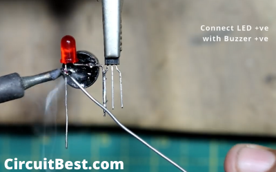
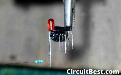
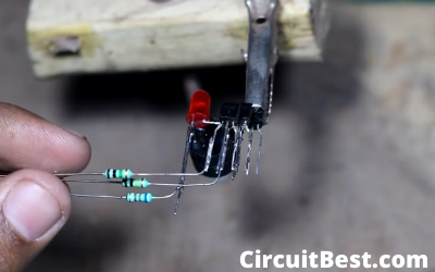
Steps for making the Circuit:
Here are Some Pictures for making the Circuit. I have made the Non-Contact AC Voltage Detector as simple as possible. You can also make the circuit in the Breadboard. But there may be loose connection So I have Directly Soldered all Components. So, there will not be any loose connection.

Note:
Please handle the Transistor’s with care if you mistakenly give high raw voltage into Transistor then it will blow up the AC Voltage Detector Circuit immediately without any indication.
While testing the AC voltage you should not touch the AC lines. Because this is very dangerous it can kill you. So, be careful about A supply. You can use any basic NPN Transistor for this project like BC547 as well as BC548.
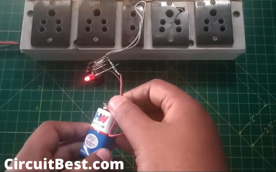
I just have soldered components. You can use a Dot PCB for making this board. AC Voltage Detector will also work on the Breadboard. It will be more professional. If you don’t have the 9V Battery 🔋 then you can use any type of power supply about 9 to 12V.
Check out the video tutorial of our sponsor channel Creative Creator for more information and interesting updates. You can use the Heat shrink tube for securing all the necessary connections.
I hope the AC Voltage Detector Circuit project will be a clear success about them who are making this Project. If you have any queries then you should definitely comment in the comment section below. I will definitely try to answer your all questions. If you like this article then you can share the articles with your friends.
You can also read our other article Custom YouTube Play button for 50,000 Subscribers.