
Introduction:
Today we are going to make a 3V LED Dimmer Circuit. Here we will use a BC547 NPN Transistor. You can also use any other NPN transistor as well. Make sure you should connect all the pins Correctly otherwise, the Transistor may be damaged. we will need some other complementary components for the circuit. we can vary the voltage without using 555 Timer IC with just using only a Transistor and a Potentiometer.
Needed Components:
- BC547: https://www.utsource.net/itm/p/10193715.html
- 5MM LED: https://www.utsource.net/itm/p/6831354.html
- 10k Resistor: https://www.utsource.net/itm/p/8328095.html
- 100k Potentiometer: https://www.utsource.net/itm/p/8038958.html
Tools Needed:
- Soldering Iron: https://www.utsource.net/itm/p/8423764.html
- Iron Stand: https://www.utsource.net/itm/p/7722853.html
- Nose Pliers: https://www.utsource.net/itm/p/7671655.html
- Flux: https://www.utsource.net/itm/p/8423764.html
Watch Video:
Here is the video from Creative Creator about 3v LED Dimmer Circuit. I hope you will understand Everything about the Circuit.
Schematics of the LED Dimmer:
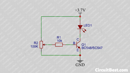
How the 3V LED Dimmer Circuit works?
The Circuit works with the basic principle of a Transistor. The Potentiometer creates a Voltage divider in the circuit. And when we rotate the Potentiometer then It creates Different voltage Levels for the LED Dimmer. These Voltage levels are sent to the Transistor’s Base with a 10k Current Limiting resistor. This resistor is important. otherwise, the Transistor would be damaged. Now the base voltage changes. For this, the Transistor flows current from Collector to Emitter. and The Loads that are connected with the transistor will be Powered Up. In this way, the 3v LED Circuit works.
Steps for making The Circuit:
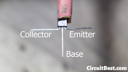
Step 1:
First, you will need an NPN Transistor. Here I am using BC548 Transistor. You can also use any other NPN Transistor as well. I bent the 3 Legs of the Transistor. Then I have Pre-tin the wires for better soldering. In the picture, you can see the Pin output.
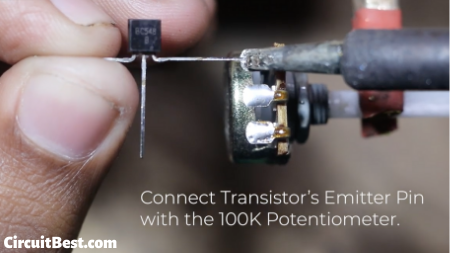
Step 2:
Now you will need a 100k Potentiometer. Connect the Transistor’s Emitter Pin with the Potentiometer corner Pin.
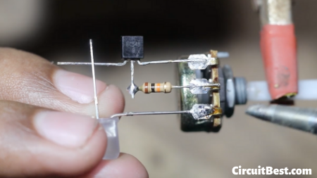
Step 3:
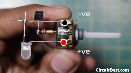
Connect LED with the circuit. Connect LED +ve with Potentiometer. And connect LED -ve with the collector of the Transistor.
Step 4:
Here are the connection points of the circuit. the voltage will be according to the load. Here I will connect 3v LED so I decided to connect with 3.7v 18650 Battery. if you have 12v loads then you can connect 12v as well.
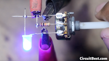
Step 5:
So, Lets Test the LED Dimmer Circuit.
You can also visit our other article about Simple Inverter Circuit.
Hello there! This article could not be written much better!
Looking at this article reminds me of my previous roommate!
He always kept preaching about this. I am going to forward this post to him.
Fairly certain he’ll have a great read. Many thanks for sharing!