

Introduction:
This is a simple inverter circuit based upon 13007 Transistor. The Basic Inverter works on the Push-Pull configuration. This Inverter is good for small loads like 15w LED Bulbs, Mobile Phone charger, and other Electrical Accessories.
Needed Components:
- 13007 Transistor: https://www.utsource.net/itm/p/4011846.html
- 330 Ohm Resistor: https://www.utsource.net/itm/p/8445643.html
- 220v to 12-0-12 Transformer: https://www.utsource.net/itm/p/8847828.html
- 12V Battery: https://www.utsource.net/itm/p/8938326.html
- 15w LED Bulb: https://www.utsource.net/itm/p/8938326.html
Tools Needed:
- Soldering Iron: https://www.utsource.net/itm/p/8423764.html
- Iron Stand: https://www.utsource.net/itm/p/7722853.html
- Nose Pliers: https://www.utsource.net/itm/p/7671655.html
- Flux: https://www.utsource.net/itm/p/8423764.html
Watch YouTube Video:
Here is the video about Simple Basic Inverter Circuit Diagram from Creative creator. So, watch the video and you will get all the points.
How the Inverter Circuit Works?
- The Inverter circuit is basically an Example of the Push-Pull Circuit.
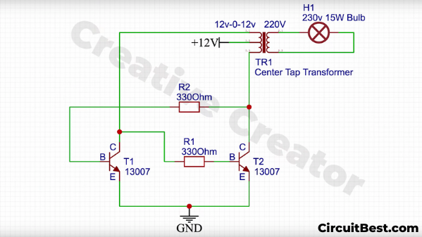
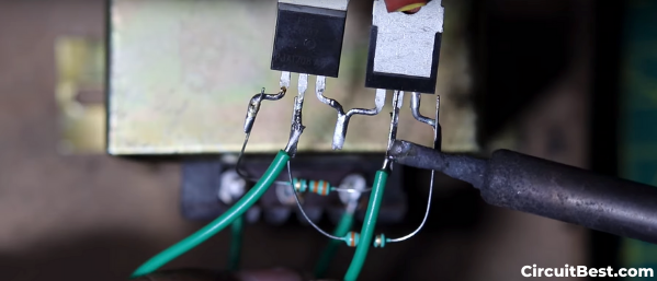
- Here I have used 13007 transistors. These transistors are connected like in the Pic:1. I have connected a 12-0-12 Transformer with the Tramsictor like in the Pic.
- when we give 12V to the circuit then One transistor became conductive at a time. for this reason, one half of the transformer’s coil became conductive. Then it reaches its saturation state and its T1 Breakdown stage occurs and the T2 Transistor became conductive. This whole thing repeats over and over. This whole process is called Push-Pull Configuration.
- This Push-Pull configuration makes Square wave Pulses at the primary of the Transformer. This Induces Flux in the Transformer. Mutual Inductance will occur. Now, the Secondary coil will be conducive for the Mutual Inductance. From this coil, we get the 220V Output.
12v to 230v inverter circuit diagram:
Connection and Testing for Simple Inverter:
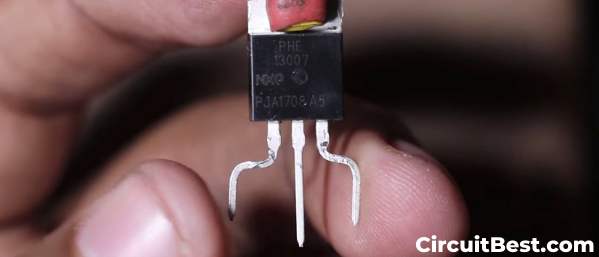
Step 1:
Bend the 13007 Transistor Pins and tin the wires for Better Soldering.
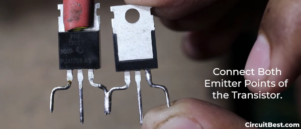
Step 2:
Connect the T1, T2 Transistor’s Emitter together for the 12v inverter circuit.
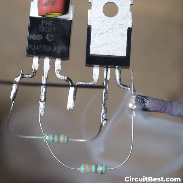
Step 3:
Now connect 330 Ohm resistor as shown in the Figure. One Transistor’s Base will be connected with the Collector of another transistor. And other Vice Versa.
Step 4:
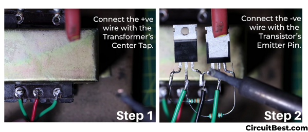
Connect the T1, T2 Transistor’s Collector with the center tap Transformer. In this case, The transformer corner points will be utilized. The center tap i.e. middle pin will not be connected in this 12v to 230v inverter circuit diagram.
Step 5:
Now Let’s talk about Input power. Here I will use a 12V LEAD ACID BATTERY. You can also use other batteries such as Lipo, LI-on as well. The Center tap point of the Transformer will be used for the +12v supply. The Emitter pin of the Transistor is for the GND or the -ve.
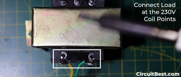
Step 6:
Now connect the External Load with the Secondary of the Transformer. Here I have used a 15W LED Bulb as a Load.
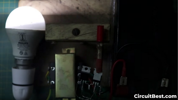
Step 7:
Let’s test it. Here I have connected a 12v Battery as a DC Input Voltage Source. Here you can see the LED is Glowing. So, the circuit works flawlessly.
You can also read another article about Simple LED Flasher Circuit with IRFZ44N MOSFET