Introduction:
Today in this article we are going to discuss how to make a simple Long Distance Transmission System circuit. So, let me give you a brief description of the circuit. How Generally all this works and How I am representing the things to you guys with some of the simple components available in our locality. This is an easy circuit based upon simple transistors and some resistors.
Concept:
Suppose I want to control a motor with a switch. So, I will just need a motor and a Switch. And The connection will be like this in the picture. The Motor and the switch will be connected in series and after that, The outer terminals will be connected with mains Supply with 110V or 220V depending on your country. Here our target is long-range so what we can do is extend the switch wires.
Flaws:
It is an easy circuit. Isn’t it? Now there are several flaws of the circuit. Here I want to run High Loads like a Motor. So I will need to use high gauge wires for connecting with the switch. And You know what High Gauge wire is not so cheap They are very expensive.
And another main flaw is the resistive loss. Let me tell you in detail. When the range is increasing then the wire length is also increasing. So there will be a High resistive loss of the wire. So, these are 2 main deficiencies of the circuit.
Solution:
For removing all these losses I just came up with this simple solution. I will make a simple circuit that will be connected at the load side. The circuit will just take a signal for turning on/ off the Motor.
Watch YouTube Video:
Schematics & Overview:
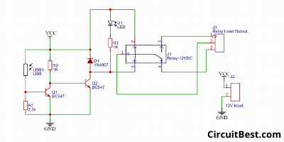
Let me give you a simple overview of the system. This circuit is based upon simple transistors. Here I have used LDR as a Light sensor and a Relay as a switch. The relay is a digital switch that can handle the maximum current.
If the light falls on LDR then the relay is off. And if the LDR is in Dark then the Relay will be on.
Here we will give light to the LDR through an external light source such as LED. Now if we turn On/ Off the led, then the Relay will be off/ on. The LED takes a maximum of 20mA of current So you can use any normal wire for powering the LED.
How does the Long Distance Transmission System Circuit work?
So, Here is the simple Schematics of the circuit. The LDR and the 2.2k resistor creates a voltage divider. At first, suppose that the LDR is not getting light. Then the Resistance of the LDR will be infinite. So, not current will flow from Q1 Transistor. This time current flows from Vcc to Q2 Transistor’s Base through 1k Resistor. It Activates the Q2 Transistor. The Load which is connected with the Q2 Transistor will be powered up.
Reversely, if the LDR Gets light then the Q1 became conductive and all current flows through the shortest path that is VCC to GND 1k Resistor. No current will flow into the Q2 Transistor’s Base. So, It won’t trigger the Q2 Transistor as well as the Relay.

Circuit Complexity:
Ok, Guys All things aside, I converted the schematics to PCB and ordered it from NextPCB.com. This is a great company for Low Budget PCBs. They are providing some of the most innovative printed circuit boards with the highest quality standards. They offer 4 layers PCBs only for 28$
Just Upload Your Garber file today. Currently, they are offering 100 by 100cm 10 PCBs for free to their New registered Customers. Processing time is 48 Hours and shipping time is also very Quick.
And wait Because of COVID-19, NextPCB is giving an exclusive 10% Discount on their PCBs and PCB Assembly Orders. so why you are waiting for? Place your first order from NextPCB.com.
Steps for making the Circuit:
Step 1:
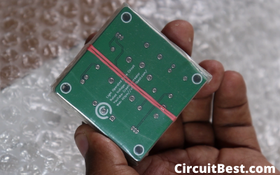
Within 5 days I received My PCBs. here you can see the quality it is great. Then I Gahererd all the components. I Placed the components on the PCB. Now I Used a fine soldering Bit. Soldered all the components in the PCB. Then I washed the PCB with Thinner.
Step 2:
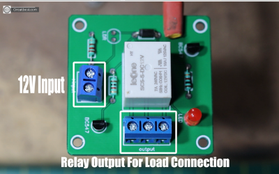
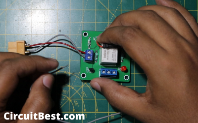
Here you can see 2 Screw terminal Blocks. This 2 Pin Screw Terminal is for 12V Power Supply. Here I am using the 12v Switch mode Power supply. And the 3 Pin Screw Terminal is for the Relay Output. The Load which we want to control will be connected here.
Step 3:
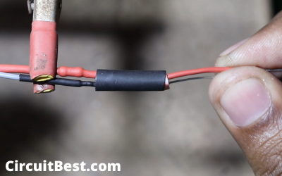
Ok so now the most important part the sensor part. For the lighting, I am using A Simple White LED. And also I want to run the LED with 12v So, I have added a 1k resistor in series with the LED. At next we have to connect the LDR and the LED in such a way that the Light of the LED Directly falls on the LDR and the surrounding Brightness will not affect this process. So, I have covered this whole thing in the black Heat Shrinking tube and nothing will create an obstacle.
Step 4:
So now I would Connect a Switch in series with the LED. If the Switch is on then the Load circuitry will work. At next I connected the LDR on the PCB and glued it with the relay. Then I soldered the LDR Terminals and the PCB is finally complete. Here I will use 12V Lipo battery so I am connecting the XT60 connector with the Input Screw terminal block of the circuit. At next, I would connect the LED -ve wire with the GND.
Step 5:
Now I would solder long wires with the switch. Then I connected the switch wire with the LED +ve and used Electrical tape for avoiding any short circuit. At next I connected the remaining switch wire with the +ve of the Input.
Testing:
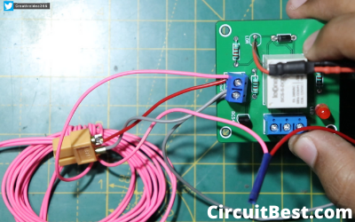
For testing, I used light as a load. So, I connected the Holder wires with the relay terminal in series. Now I have connected the 12v battery for giving power to the circuit. After that, I connected the lead wire with the ac supply And here you can see the circuit works just fine.
Conclusion:
So, all in all, this is a pretty fun project to make. I hope you guys like my take on the Long Distance Transmission System. I hope you guys knew something new from this post. All components are pretty cheap you can buy it from any shop. I highly suggest you make it in your Quarantine period.
You can also read our other article about Arduino LED Chaser Circuit Here.