

Introduction:
In this short article, we are going to learn how to make a DC motor speed control circuit. Mainly we are going to learn how the circuit works and what is about the PWM signal? and how the PWM signal is used to control the DC motor speed.
Concept:
DC motor is a purely inductive Load so if you want to control the speed of the DC motor then we have to upper / lower the voltage for higher / lower speeds. but in practically higher voltage and lower voltage is not that type of possible so in this case, we use another type of method which is called PWM better known as pulse width modulation.
Needed Components for LED Dimmer Circuit:
- IRFZ44N: https://www.utsource.net/itm/p/9223667.html
- LED: https://www.utsource.net/itm/p/6831354.html
- Resistor: https://www.utsource.net/itm/p/8328095.html
- Capacitor: https://www.utsource.net/itm/p/1898386.html
Tools Needed:
- Soldering Iron: https://www.utsource.net/itm/p/8423764.html
- Iron Stand: https://www.utsource.net/itm/p/7722853.html
- Nose Pliers: https://www.utsource.net/itm/p/7671655.html
- Flux: https://www.utsource.net/itm/p/8423764.html
YouTube Video:
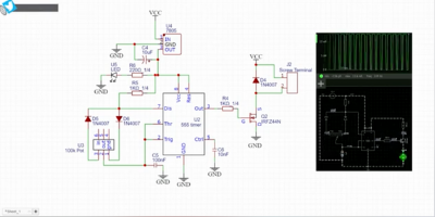
Watch the YouTube video for step by step guide.
Circuit Schematics:
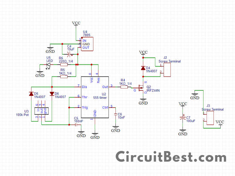
Here are the schematics of the DC Motor Speed Control Circuit.
What is PWM?
The word PWM is also known as Pulse Width Modulation. Suppose there is a voltage of 5 volts which is turning on and off in an interval. This on / off signal is mainly presented as duty cycles now if there is 50% duty cycle in the output voltage will be 50% of 5 volts so it will be nearly 2.5 volts. The duty cycle can be 25% of 50% or 90% or even 100%. so now you can calculate what the voltage will be when the duty cycle will be in a certain percentage. Now this PWM Pulses runs the transistor and it runs the Motor.
How does the Motor Speed Control circuit work?
This is a very basic circuit that is made up of 555 timer IC which will produce Square wave Pulses.
There are so many complementary components for generating PWM pulses from the 555 timer IC.
for changing the duty cycles of the PWM pulses we are using a 100K potentiometer.
The Pin no 3 of the 555 timer IC provides PWM pulses these pulses are not strong enough to run a DC motor. So what we need to do is to amplify the signal.
For the amplification of the circuit, we have used N-channel MOSFET IRFZ44N. The gate pin of the MOSFET is connected with the No 3 pin of the 555 timers through a resistor.
When the MOSFET gets High PWM pulses then the duty cycle should be high so it means more current will flow from drain to source so in this case, the motor will Speed Up in the fastest speed.
The same case happens when the PWM pulse is low. In the low duty cycles, the transistor will be switched in very low frequency. So, for this reason, the motor speed will be low in this case.
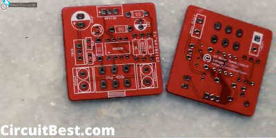
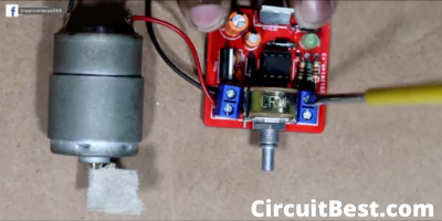
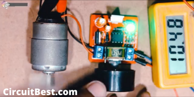
Steps for making the Circuit:
Here are Some Pictures for making the Circuit. I have made the DC Motor Speed Controller Circuit in the PCB for making the circuit as simple as possible. You can also make the circuit in the Breadboard. But there may be loose connection So I have Directly Soldered all Components. So, there will not be any loose connection.
Note:
Here I have used IRFZ44N n channel MOSFET which is capable of high amperes. But you can also use any type of N-Channel MOSFETs. The ampere rating may be very for other MOSFETs.
555 timer IC needs a constant voltage so here I have used 7805 IC for constant voltage from 7 to 35 volt. You can also use any voltage like 5 volts to 15 volts for that 555 timer IC.
I have connected a diode in parallel with the motor. This is for the back EMF Protection of the motor. This will not damage the MOSFET from Back EMF. This is mandatory.
You Can also read our another article: Click Here