Introduction:
Today in this article we are going to Discuss the Relay module. Here I will make a 12 Channel relay Board. This relay board connects through Bluetooth. And most importantly, you can control room lights/ all loads with a single touch of your Phone. so, likely many users will like it if they don’t have any valid IR sensor in the Phone. The Brain of this Project is Arduino. So, basically, you will learn how to write a simple Arduino code.
For the components section, I have gone with UTSOURCE. They are one of the largest component suppliers in China. They offer different types of components such as Resistors, Capacitors, ICs and many other things. You will get exclusive discounts If you order from them. So, why you are waiting for? Place your first order from UTSOURCE.
0 Profit selling KN95 masks and Infrared Thermometer from UTSOURCE.net: https://www.utsource.net/home/healthcare
Components needed:
- Arduino Nano: https://www.utsource.net/itm/p/9221680.html
- HC-05 Bluetooth: https://www.utsource.net/itm/p/7566177.html
- Relay: https://www.utsource.net/itm/p/9510225.html
- 12V Adapter: https://www.utsource.net/itm/p/9221236.html
- Resistors: https://www.utsource.net/itm/p/8328095.html
- Capacitor: https://www.utsource.net/itm/p/1872752.html
- Screw Terminal Block: https://www.utsource.net/itm/p/612970.html
- Female Header: https://www.utsource.net/itm/p/8297352.html
- 5MM Green LED: https://www.utsource.net/itm/p/9942990.html
- 5MM Red LED: https://www.utsource.net/itm/p/9942990.html
- Push Button: https://www.utsource.net/itm/p/8406560.html
- LED Bulbs: https://www.utsource.net/itm/p/9942990.html
- Wires: https://www.utsource.net/itm/p/9221308.html
- BC547 Transistor: https://www.utsource.net/itm/p/6964442.html
- 1N4007 Diode: https://www.utsource.net/itm/p/300046.html
- Soldering Iron: https://www.utsource.net/itm/p/8368922.html
- Arduino Uno R3 Board: https://www.utsource.net/itm/p/7281975.html
Tools Needed:
- Soldering Iron: https://www.utsource.net/itm/p/8423764.html
- Iron Stand: https://www.utsource.net/itm/p/7722853.html
- Nose Pliers: https://www.utsource.net/itm/p/7671655.html
- Flux: https://www.utsource.net/itm/p/8423764.html
Watch YouTube Video:
Here is the video about the 12 Channel Bluetooth Controlled Relay Module with Arduino Nano. Watch the video till the End you will understand Everything. It is very easy to control the room lights.
Circuit Schematics:
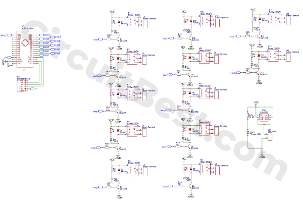
I have made the circuit diagram on Online free Software EasyEDA. I have also used some nodes for making the connections simple.
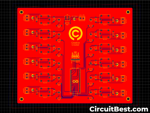
There are many components in the circuit. Keeping all things in my mind I have also created a suitable PCB for the circuit. I ordered it from JLCPCB. Here is the PCB Front Layout.
How does the 12 Channel relay Board work to control room lights?
The main heart of this project is Arduino Nano. And for the wireless communication, I am using an HC05 Bluetooth Module. And for handling the High loads I am using 12 Relays couple with some driving transistors.
And lastly, for controlling the circuit we will need an app. BTW I have designed an application from MITApp Inventer for this project.
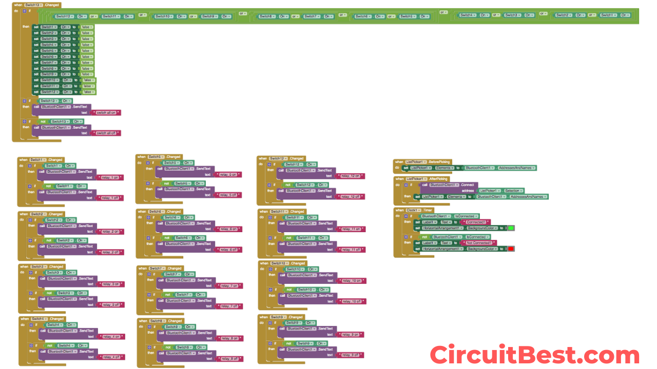
Blocks:
Here are all the respective blocks for making the app. If you are designing the app for yourself then this might can help you. Here I used Toggle Button So the Code is a bit long I think in my opinion. You can also use some simple push buttons in the app. The Pushbuttons will minimize the Code. But In my case, I find that the Toggle Buttons look more prominent from Pushbuttons.
At next Let’s Talk about the circuit. I mean How the 12 Channel relay module works? The Arduino has digital pins as well as analog pins. Here I have used all digital pins which are I think in total is 12. I used all of them.
The Digital pins give High or Low Pulses. High means 1 and the Low means 0. The High pulses turn the Driver Transistor on and then the Driver Transistor turns the relays on for loads.
How does the Wireless Connectivity work to Control Your Room Lights With Your Phone?
The wireless connection is done through HC05 Bluetooth Module. When you turn the Switch on from the phone then the app sends a Massage to the Arduino through HC05. Then we have added a couple of ‘It-Else’ conditions. Now for a single massage, A single line will be executed. If this doesn’t satisfy the condition then it will automatically switch to next ‘If-Else’ condition. In this way, the condition satisfies and the relays will be on for loads.
Steps For Making 12 Channel Relay Module:
Step 1:
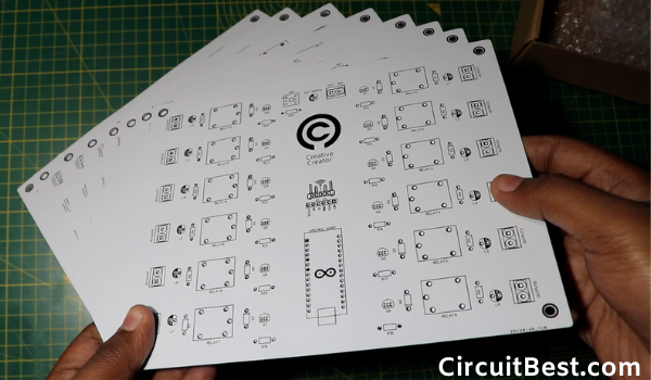
The project has high complexity if I make the circuit on Breadboard or zero PCB. Because of this complexity, I have gone with Custom Designed PCB from JLCPCB. They are also sponsoring for this Project. After one week later, I received my PCB package from JLCPCB.

Step 2:
At next I have checked Solder pads connections. And the one thing I have to say is that the PCB quality is extraordinary. If you have Big projects in your mind then checkout JLCPCB at least one time.
Step 3:
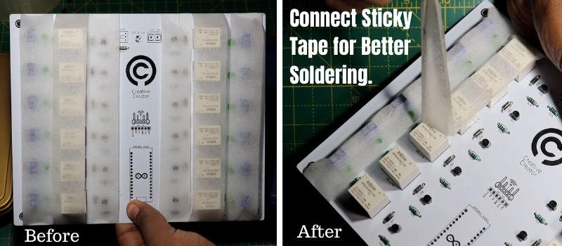
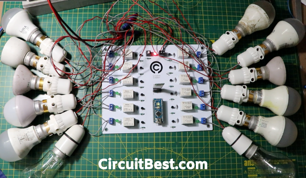
Then I gathered all the components and placed all the components in the PCB. Then I soldered all the components into the PCB.

Note:
I have used Sticky Tape for fixing all the components in its place. For this reason, the components will not move from its place. After the Soldering process completes we can remove the Sticky Tape.
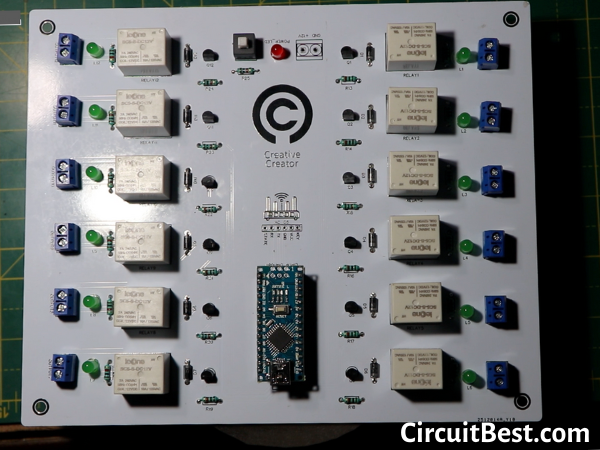
After removing all the Sticky Tabe the PCB looks very great. Here is the closeup of the PCB. Soldering Process is very easy because of Pre soldered copper traces.
Step 4:
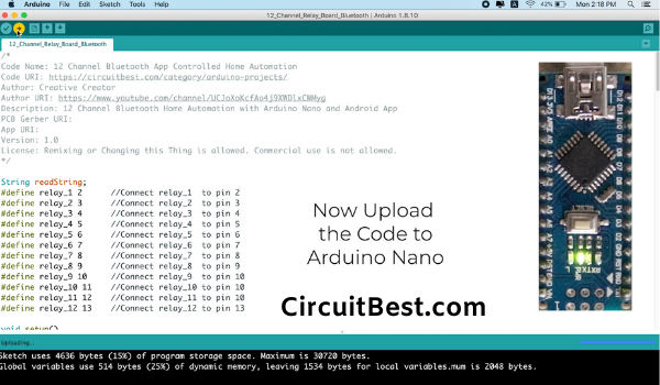
Let’s program the Arduino Nano. I have connected the USB with Arduino Nano and my Mac. Then I compiled it first. Next, I uploaded the code to Arduino. One thing you should really take care of. If you connect the Bluetooth Module while uploading the code. Then the code will not be uploaded. It will show you some types of Error. So, It is always recommended to remove Bluetooth connectivity before uploading the Code.
Step 5:
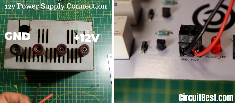
Then I attached Bluetooth Module HC-05 and the Arduino Nano to the PCB. Now let’s connect power with the circuit. I have designed the circuit to work with 12v. so, first I connected 12v +ve and GND wires with the PCB. Then I connected the other end of the wires with 12v Power supply. Here I am using a 12V Computer Power Supply.
App:
Currently, My app is only available for Android users. If I design the app for iOS then I will update this later.
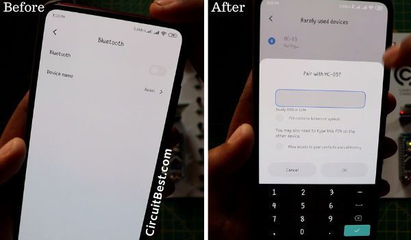
For now open Bluetooth in your Android Device. Then look for HC05 Bluetooth. The default password for the Bluetooth is 1234 or 0000. Most of the time, the password is 1234.
Now give the password and connect with your Bluetooth.
Step 6:
At next Download the app from the description. And install it to your Android Phone. You may have to give permission from Unknown Sources. Just allow the settings and Install the app.
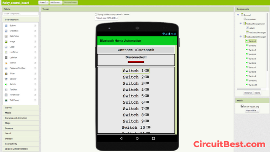
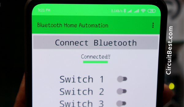
Now open the app and click on the Connect Button. Now from the given menus select the HC05 Bluetooth.
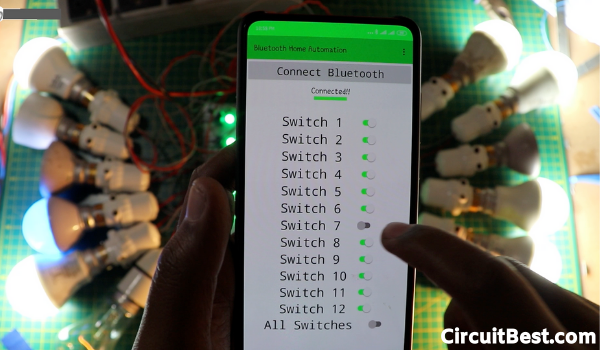
For the first time when you have not connected to the Bluetooth then the Bar color will be Red. After you connect the Bar will be Green.
In this way, you can identify if the HC05 Bluetooth module is connected or not.
Below the “Connect to Bluetooth” Button you will find 12 Toggle buttons. These toggle buttons are used for switching On/Off the Relays.
At last but not least I have also added all at once switch. If you press the switch then all relays will be turned on all at a time.
There are all the specifications of the app. Of course, you can add more switches by adding few more Functions. But I want to make the project as simple as possible.
Step 7:
Load Connection: Now let’s attach loads with the circuit. As you guys know the PCB contains 12 Relays so, we can easily connect 12 Loads with the circuit.
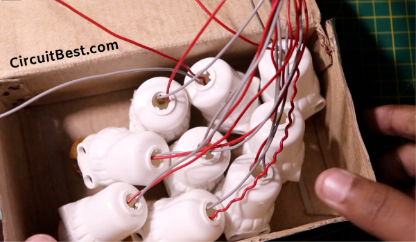
First I took 12 Holders for 12 lights. Then I have connected the Holders with series with the relay. And the connection terminal will go to the mains voltage.
In this same way, I have connected all the Light Holders with the relays. Now for the AC power Input, I have used one 2 pin plug and connected all 12 pairs of wires in parallel.
Step 8:
Now I turned on the 12V power Supply then I turned on the 230v AC Power Supply for the consequent loads. Then connected the app with Bluetooth. Then Turned on some of the toggle switches as you can see the Loads are working flawlessly.
Code:
/*
Code Name: 12 Channel Bluetooth App Controlled Home Automation
Code URI: https://circuitbest.com/category/arduino-projects/
Author: Creative Creator
Author URI: https://www.youtube.com/channel/UCJoXoKcfAo4j9XWDlxCWMyg
Description: 12 Channel Bluetooth Home Automation with Arduino Nano and Android App
PCB Gerber URI: http://bit.ly/2UnIFFb
App URI: http://bit.ly/2OvxeaG
Version: 1.0
License: Remixing or Changing this Thing is allowed. Commercial use is not allowed.
*/

String readString;
#define relay_1 2      //Connect relay_1  to pin 2
#define relay_2 3      //Connect relay_2  to pin 3
#define relay_3 4      //Connect relay_3  to pin 4
#define relay_4 5      //Connect relay_4  to pin 5
#define relay_5 6      //Connect relay_5  to pin 6
#define relay_6 7      //Connect relay_6  to pin 7
#define relay_7 8      //Connect relay_7  to pin 8
#define relay_8 9      //Connect relay_8  to pin 9
#define relay_9 10     //Connect relay_9  to pin 10
#define relay_10 11    //Connect relay_10 to pin 10
#define relay_11 12    //Connect relay_11 to pin 10
#define relay_12 13    //Connect relay_12 to pin 13

void setup()
{
  Serial.begin(9600);             //Set rate for communicating with phone
  pinMode(relay_1, OUTPUT);       //Set relay_1  as an output
  pinMode(relay_2, OUTPUT);       //Set relay_2  as an output
  pinMode(relay_3, OUTPUT);       //Set relay_3  as an output
  pinMode(relay_4, OUTPUT);       //Set relay_4  as an output
  pinMode(relay_5, OUTPUT);       //Set relay_5  as an output
  pinMode(relay_6, OUTPUT);       //Set relay_6  as an output
  pinMode(relay_7, OUTPUT);       //Set relay_7  as an output
  pinMode(relay_8, OUTPUT);       //Set relay_8  as an output
  pinMode(relay_9, OUTPUT);       //Set relay_9  as an output
  pinMode(relay_10, OUTPUT);      //Set relay_10 as an output
  pinMode(relay_11, OUTPUT);      //Set relay_11 as an output
  pinMode(relay_12, OUTPUT);      //Set relay_12 as an output


  digitalWrite(relay_1, LOW);     //Switch relay_1  off
  digitalWrite(relay_2, LOW);     //Swtich relay_2  off
  digitalWrite(relay_3, LOW);     //Switch relay_3  off
  digitalWrite(relay_4, LOW);     //Swtich relay_4  off
  digitalWrite(relay_5, LOW);     //Swtich relay_5  off
  digitalWrite(relay_6, LOW);     //Swtich relay_6  off
  digitalWrite(relay_7, LOW);     //Swtich relay_7  off
  digitalWrite(relay_8, LOW);     //Swtich relay_8  off
  digitalWrite(relay_9, LOW);     //Swtich relay_9  off
  digitalWrite(relay_10, LOW);    //Swtich relay_10 off
  digitalWrite(relay_11, LOW);    //Switch relay_11 off
  digitalWrite(relay_12, LOW);    //Swtich relay_12 off

}
void loop()
{
  while(Serial.available())             //Check if there are available bytes to read
  {
    delay(10);                          //Delay to make it stable
    char c = Serial.read();             //Conduct a serial read
    if (c == '#'){
      break;                            //Stop the loop once # is detected after a word
    }
    readString += c;                    //Means readString = readString + c
  }
    if (readString.length() >0)
    {
      Serial.println(readString);
      if(readString == "switch all on"){
        allSwitchesOn();
      }
      else if(readString == "switch all off"){
        allSwitchesOff();
      }
      else if(readString == "relay_1 on"){
        digitalWrite(relay_1, HIGH);
      }
      else if(readString == "relay_1 off"){
        digitalWrite(relay_1, LOW);
      }
       else if(readString == "relay_2 on"){
        digitalWrite(relay_2, HIGH);
      }
      else if(readString == "relay_2 off"){
        digitalWrite(relay_2, LOW);
      }
       else if(readString == "relay_3 on"){
        digitalWrite(relay_3, HIGH);
      }
      else if(readString == "relay_3 off"){
        digitalWrite(relay_3, LOW);
      }
      else if(readString == "relay_4 on"){
        digitalWrite(relay_4, HIGH);
      }
      else if(readString == "relay_4 off"){
        digitalWrite(relay_4, LOW);
      }
      else if(readString == "relay_5 on"){
        digitalWrite(relay_5, HIGH);
      }
      else if(readString == "relay_5 off"){
        digitalWrite(relay_5, LOW);
      }
      else if(readString == "relay_6 on"){
        digitalWrite(relay_6, HIGH);
      }
      else if(readString == "relay_6 off"){
        digitalWrite(relay_6, LOW);
      }
      else if(readString == "relay_7 on"){
        digitalWrite(relay_7, HIGH);
      }
      else if(readString == "relay_7 off"){
        digitalWrite(relay_7, LOW);
      }
      else if(readString == "relay_8 on"){
        digitalWrite(relay_8, HIGH);
      }
      else if(readString == "relay_8 off"){
        digitalWrite(relay_8, LOW);
      }
      else if(readString == "relay_9 on"){
        digitalWrite(relay_9, HIGH);
      }
      else if(readString == "relay_9 off"){
        digitalWrite(relay_9, LOW);
      }
      else if(readString == "relay_10 on"){
        digitalWrite(relay_10, HIGH);
      }
      else if(readString == "relay_10 off"){
        digitalWrite(relay_10, LOW);
      }
      else if(readString == "relay_11 on"){
        digitalWrite(relay_11, HIGH);
      }
      else if(readString == "relay_11 off"){
        digitalWrite(relay_11, LOW);
      }
            else if(readString == "relay_12 on"){
        digitalWrite(relay_12, HIGH);
      }
      else if(readString == "relay_12 off"){
        digitalWrite(relay_12, LOW);
      }
      readString="";
    }
}
void allSwitchesOff()               //Function for turning OFF all relays
{
  digitalWrite(relay_1, LOW);       //Switch relay_1  off
  digitalWrite(relay_2, LOW);       //Swtich relay_2  off
  digitalWrite(relay_3, LOW);       //Switch relay_3  off
  digitalWrite(relay_4, LOW);       //Swtich relay_4  off
  digitalWrite(relay_5, LOW);       //Swtich relay_5  off
  digitalWrite(relay_6, LOW);       //Swtich relay_6  off
  digitalWrite(relay_7, LOW);       //Swtich relay_7  off
  digitalWrite(relay_8, LOW);       //Swtich relay_8  off
  digitalWrite(relay_9, LOW);       //Swtich relay_9  off
  digitalWrite(relay_10, LOW);      //Swtich relay_10 off
  digitalWrite(relay_11, LOW);      //Swtich relay_11 off
  digitalWrite(relay_12, LOW);      //Swtich relay_12 off
}
void allSwitchesOn()                //Function for turning ON all relays
{
  digitalWrite(relay_1, HIGH);      //Swtich relay_1  off
  digitalWrite(relay_2, HIGH);      //Swtich relay_2  off
  digitalWrite(relay_3, HIGH);      //Swtich relay_3  off
  digitalWrite(relay_4, HIGH);      //Swtich relay_4  off
  digitalWrite(relay_5, HIGH);      //Swtich relay_5  off
  digitalWrite(relay_6, HIGH);      //Swtich relay_6  off
  digitalWrite(relay_7, HIGH);      //Swtich relay_7  off
  digitalWrite(relay_8, HIGH);      //Swtich relay_8  off
  digitalWrite(relay_9, HIGH);      //Swtich relay_9  off
  digitalWrite(relay_10, HIGH);     //Swtich relay_10 off
  digitalWrite(relay_11, HIGH);     //Swtich relay_11 off
  digitalWrite(relay_12, HIGH);     //Swtich relay_12 off
}
Download Links:
- Schematics: Download
- PCB Image: Download
- Home Automation PCB Garber: Download
- App Inventor Block Image: Download
- Arduino Bluetooth Home Automation Code: Download
- Home Automation App: Download
- App Aia File Download
Conclusion:
So, all in all, I can say it is a fun project, to begin with. But I faced some difficulties while making the project. Such as making the app. I am not an app developer from my background. So, it took a lot of time. But at last, I came up with a fully working 12 channel relay module circuit with Bluetooth. I will thank JLCPCB for making this video possible. Otherwise, there are too many connections. Attaching all this circuit in a breadboard is like pain in the ass. So we can declare the project a great success. All schematics, PCB design, PCB fabrication file, Arduino Code, app Inventor blocks all are given in the description. I hope you guys like my take on the 12 channel relay module Board with Arduino Nano.
You can also read our other articles about Arduino.
Control Your Room Lights With Your Phone
/*
Code Name: 12 Channel Bluetooth App Controlled Home Automation
Code URI: https://circuitbest.com/category/arduino-projects/
Author: Creative Creator
Author URI: https://www.youtube.com/channel/UCJoXoKcfAo4j9XWDlxCWMyg
Description: 12 Channel Bluetooth Home Automation with Arduino Nano and Android App
PCB Gerber URI: http://bit.ly/2UnIFFb
App URI: http://bit.ly/2OvxeaG
Version: 1.0
License: Remixing or Changing this Thing is allowed. Commercial use is not allowed.
*/

String readString;
#define relay_1 2      //Connect relay_1  to pin 2
#define relay_2 3      //Connect relay_2  to pin 3
#define relay_3 4      //Connect relay_3  to pin 4
#define relay_4 5      //Connect relay_4  to pin 5
#define relay_5 6      //Connect relay_5  to pin 6
#define relay_6 7      //Connect relay_6  to pin 7
#define relay_7 8      //Connect relay_7  to pin 8
#define relay_8 9      //Connect relay_8  to pin 9
#define relay_9 10     //Connect relay_9  to pin 10
#define relay_10 11    //Connect relay_10 to pin 10
#define relay_11 12    //Connect relay_11 to pin 10
#define relay_12 13    //Connect relay_12 to pin 13

void setup()
{
  Serial.begin(9600);             //Set rate for communicating with phone
  pinMode(relay_1, OUTPUT);       //Set relay_1  as an output
  pinMode(relay_2, OUTPUT);       //Set relay_2  as an output
  pinMode(relay_3, OUTPUT);       //Set relay_3  as an output
  pinMode(relay_4, OUTPUT);       //Set relay_4  as an output
  pinMode(relay_5, OUTPUT);       //Set relay_5  as an output
  pinMode(relay_6, OUTPUT);       //Set relay_6  as an output
  pinMode(relay_7, OUTPUT);       //Set relay_7  as an output
  pinMode(relay_8, OUTPUT);       //Set relay_8  as an output
  pinMode(relay_9, OUTPUT);       //Set relay_9  as an output
  pinMode(relay_10, OUTPUT);      //Set relay_10 as an output
  pinMode(relay_11, OUTPUT);      //Set relay_11 as an output
  pinMode(relay_12, OUTPUT);      //Set relay_12 as an output


  digitalWrite(relay_1, LOW);     //Switch relay_1  off
  digitalWrite(relay_2, LOW);     //Swtich relay_2  off
  digitalWrite(relay_3, LOW);     //Switch relay_3  off
  digitalWrite(relay_4, LOW);     //Swtich relay_4  off
  digitalWrite(relay_5, LOW);     //Swtich relay_5  off
  digitalWrite(relay_6, LOW);     //Swtich relay_6  off
  digitalWrite(relay_7, LOW);     //Swtich relay_7  off
  digitalWrite(relay_8, LOW);     //Swtich relay_8  off
  digitalWrite(relay_9, LOW);     //Swtich relay_9  off
  digitalWrite(relay_10, LOW);    //Swtich relay_10 off
  digitalWrite(relay_11, LOW);    //Switch relay_11 off
  digitalWrite(relay_12, LOW);    //Swtich relay_12 off

}
void loop()
{
  while(Serial.available())             //Check if there are available bytes to read
  {
    delay(10);                          //Delay to make it stable
    char c = Serial.read();             //Conduct a serial read
    if (c == '#'){
      break;                            //Stop the loop once # is detected after a word
    }
    readString += c;                    //Means readString = readString + c
  }
    if (readString.length() >0)
    {
      Serial.println(readString);
      if(readString == "switch all on"){
        allSwitchesOn();
      }
      else if(readString == "switch all off"){
        allSwitchesOff();
      }
      else if(readString == "relay_1 on"){
        digitalWrite(relay_1, HIGH);
      }
      else if(readString == "relay_1 off"){
        digitalWrite(relay_1, LOW);
      }
       else if(readString == "relay_2 on"){
        digitalWrite(relay_2, HIGH);
      }
      else if(readString == "relay_2 off"){
        digitalWrite(relay_2, LOW);
      }
       else if(readString == "relay_3 on"){
        digitalWrite(relay_3, HIGH);
      }
      else if(readString == "relay_3 off"){
        digitalWrite(relay_3, LOW);
      }
      else if(readString == "relay_4 on"){
        digitalWrite(relay_4, HIGH);
      }
      else if(readString == "relay_4 off"){
        digitalWrite(relay_4, LOW);
      }
      else if(readString == "relay_5 on"){
        digitalWrite(relay_5, HIGH);
      }
      else if(readString == "relay_5 off"){
        digitalWrite(relay_5, LOW);
      }
      else if(readString == "relay_6 on"){
        digitalWrite(relay_6, HIGH);
      }
      else if(readString == "relay_6 off"){
        digitalWrite(relay_6, LOW);
      }
      else if(readString == "relay_7 on"){
        digitalWrite(relay_7, HIGH);
      }
      else if(readString == "relay_7 off"){
        digitalWrite(relay_7, LOW);
      }
      else if(readString == "relay_8 on"){
        digitalWrite(relay_8, HIGH);
      }
      else if(readString == "relay_8 off"){
        digitalWrite(relay_8, LOW);
      }
      else if(readString == "relay_9 on"){
        digitalWrite(relay_9, HIGH);
      }
      else if(readString == "relay_9 off"){
        digitalWrite(relay_9, LOW);
      }
      else if(readString == "relay_10 on"){
        digitalWrite(relay_10, HIGH);
      }
      else if(readString == "relay_10 off"){
        digitalWrite(relay_10, LOW);
      }
      else if(readString == "relay_11 on"){
        digitalWrite(relay_11, HIGH);
      }
      else if(readString == "relay_11 off"){
        digitalWrite(relay_11, LOW);
      }
            else if(readString == "relay_12 on"){
        digitalWrite(relay_12, HIGH);
      }
      else if(readString == "relay_12 off"){
        digitalWrite(relay_12, LOW);
      }
      readString="";
    }
}
void allSwitchesOff()               //Function for turning OFF all relays
{
  digitalWrite(relay_1, LOW);       //Switch relay_1  off
  digitalWrite(relay_2, LOW);       //Swtich relay_2  off
  digitalWrite(relay_3, LOW);       //Switch relay_3  off
  digitalWrite(relay_4, LOW);       //Swtich relay_4  off
  digitalWrite(relay_5, LOW);       //Swtich relay_5  off
  digitalWrite(relay_6, LOW);       //Swtich relay_6  off
  digitalWrite(relay_7, LOW);       //Swtich relay_7  off
  digitalWrite(relay_8, LOW);       //Swtich relay_8  off
  digitalWrite(relay_9, LOW);       //Swtich relay_9  off
  digitalWrite(relay_10, LOW);      //Swtich relay_10 off
  digitalWrite(relay_11, LOW);      //Swtich relay_11 off
  digitalWrite(relay_12, LOW);      //Swtich relay_12 off
}
void allSwitchesOn()                //Function for turning ON all relays
{
  digitalWrite(relay_1, HIGH);      //Swtich relay_1  off
  digitalWrite(relay_2, HIGH);      //Swtich relay_2  off
  digitalWrite(relay_3, HIGH);      //Swtich relay_3  off
  digitalWrite(relay_4, HIGH);      //Swtich relay_4  off
  digitalWrite(relay_5, HIGH);      //Swtich relay_5  off
  digitalWrite(relay_6, HIGH);      //Swtich relay_6  off
  digitalWrite(relay_7, HIGH);      //Swtich relay_7  off
  digitalWrite(relay_8, HIGH);      //Swtich relay_8  off
  digitalWrite(relay_9, HIGH);      //Swtich relay_9  off
  digitalWrite(relay_10, HIGH);     //Swtich relay_10 off
  digitalWrite(relay_11, HIGH);     //Swtich relay_11 off
  digitalWrite(relay_12, HIGH);     //Swtich relay_12 off
}