
Introduction:
Hello guys, today in this article we are going to discuss how to make a led Flasher circuit with LDR. So, certainly, you can change the blink speed with the LDR Light intensity.
So this is a great circuit for a hobbyist. Easy to make. You will not need any PCBs for making the Circuit. You can just solder all the components easily and make the circuit.
This type of oscillation circuit is often known as Stable multivariate. These circuits don’t need any other outer or other oscillation for running. The oscillation is created through the Transistor’s and the capacitors and the waveform is purely squire wave, as a result, the results will be pretty great. This circuit doesn’t need any outer oscillation.
Here the Transistor is crossly coupled. And the capacitors have two different states. If one capacitor is on then another capacitor will be off. The circuit works with a feedback network. That is why it is also called Free Running Multivariator.
Needed Components:
- BC547: https://www.utsource.net/itm/p/876498.html
- 5MM LED: https://www.utsource.net/itm/p/6831354.html
- 10k Resistor: https://www.utsource.net/itm/p/8328095.html
- 18k Potentiometer: https://www.utsource.net/itm/p/8038958.html
Tools Needed:
- Soldering Iron: https://www.utsource.net/itm/p/8423764.html
- Iron Stand: https://www.utsource.net/itm/p/7722853.html
- Nose Pliers: https://www.utsource.net/itm/p/7671655.html
- Flux: https://www.utsource.net/itm/p/8423764.html
Watch Video:
Here is the Video form Creative Creator YouTube Channel and you can watch the video to the end to understand every step that I have done in the project.
How does the circuit work?
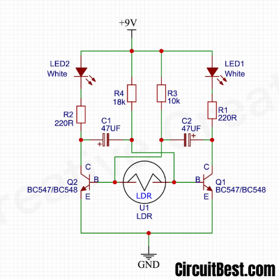
This is basically a modified astable multivibrator circuit. It is very easy. The LDR creates a voltage divider.
When the LDR and the resistors create a voltage divider. Then the intensity of the light is higher then the LDR resistor value will be lower. And when the intensity is lower then the usual then the LDR acts as an infinite resistor.
Here to capacitors are connected they work alternatively. If capacitor 1 is charged in one time then Capacitor 2 will be discharged. This works like a flip flop configuration.
The capacitor 1 discharges through transistor 2 and the capacitor 2 discharges through transistor 1. When one capacitor charges then other capacitor discharges. This is like a sequential manner.
Circuit Diagram:
Steps for making the Circuit:
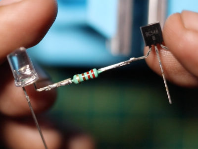
Step 1:
First, take a BC547 Transistor. Then connect a 220R resistor with the collector of the BC547 Transistor. Then connect a 5 mm led -ve with the 220R resistor.
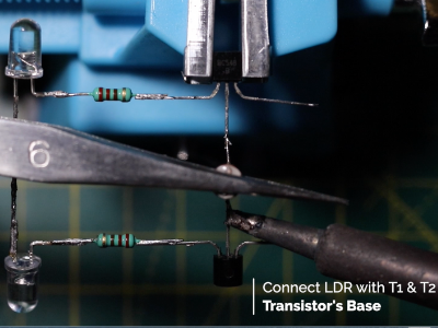
Step 2:
Make the same circuit once more. Then take an LDR and then connect two Transistor base with LDR. Now take a piece of wire and connect the two emitter pins.
Step 3:
Now take a 10k resistor and then contact one end of the LED +Ve. Now take other wire of the Resistor and connect it with the T1 Transistor’s base.
In the same way, now connect an 18k resistor. Connect one end with LED +ve and another end with T2 Transistor’s base.
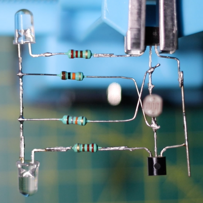
Step 4:
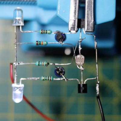
Now connect the capacitors in this manner as shown in the figure. Make sure you don’t short Anything in the circuit. Otherwise, LED Flasher Circuit with LDR will not work.
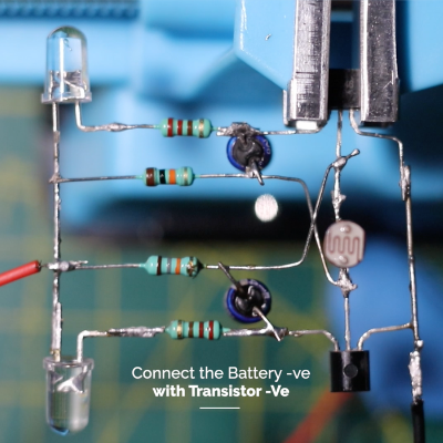
Connect the 9v battery +ve wire with the LED +ve and connect the -ve wire with the Transistor’s Emitter pin.
Step 5:
Now connect the circuit with 9v battery and then you will see the circuit will work fine. At next take a light source closer to the circuit and then you will see that the led blinking will be faster and if you take the light far away from the LDR then you can see that LED blinking will be slow.
Note:
You shouldn’t short-circuit any of the Transistors.
Connect the Transistor’s pins as shown in the picture. If you make any mistakes then there will be a high possibility of Magic Smoke.
No one likes smokes from the circuit. So be careful while making the circuit.
Conclusion:
All in all, LED Flasher Circuit with LDR is a great project for beginners. And the circuit is easy to construct. And with all basic all components anyone can make the circuit in the home. So that’s why the circuit is very helpful for Hobbyists.
You can also read another article about Simple Inverter Circuit this is also very easy to construct.