
Today in this article we are going to discuss the advantages of wire break alarm circuit with IRFZ44N MOSFET. The IRFZ44N is an N-Channel Enhancement type MOSFET to it can Deliver high Output for simple wire cut alarm. This Circuit also works with other N-Channel Mosfets as well. I will thank Utsource for sponsoring.
Wire Break Alarm Introduction:
The Wire Break alarm is kind of an Emergency Alarm Circuit. It has a loop sensor in it. The loop is a simple piece of Copper Wire for shorting two terminals. The circuit needs 9-12V for General Operation. In general, if we cut this wire then the circuit became open-circuited. There are many wire break alarm circuit applications.
The first time when the wire loop is connected than the current flows from the Vcc to GND through a 33k Resistor. Now when you cut the loop wire then the current flows from the Vcc to MOSFET’s Gate pin. So, it activates the MOSFET. As a result, the MOSFET became conductive. As a result, current flows from Drain to Source. So, the Load which is connected with the MOSFET will be powered up. You can also use this Circuit as a broken wire detector project report.
Watch Video:
Watch the video from Creative creator and you will Understand Everything about wire break alarm circuit with IRFZ44N MOSFET.
Components Lists From Utsource:
- LED: Link1
- Relay: Link1
- Buzzer: Link1
- IRFZ44N: Link1
- 9v Battery: Link1
- 9V Battery Clip: Link1
- Resistor: 33k 100R- Link1
Devices Required for Wire Break Alarm :
How does the Wire Break Alarm circuit work?
- This is a very easy circuit based on a MOSFET transistor.
- Whenever we give power to the circuit then the current flows from 33k Resistor and then from the wire loop and then goes to the GND.
- Now when you cut the loop wire then the current flows from the Vcc to MOSFET’s Gate pin.
- So, it activates the MOSFET. As a result, the MOSFET became conductive. As a result, current flows from Drain to Source. So, the Load which is connected with the MOSFET will be powered up.
- Here you must connect a current limiting Resistor. For the LEDs and the Buzzer. Otherwise, the LED may fuse.
- so these are wire break alarm circuit applications.
Construction and testing for wire break alarm circuit:
Step 1:
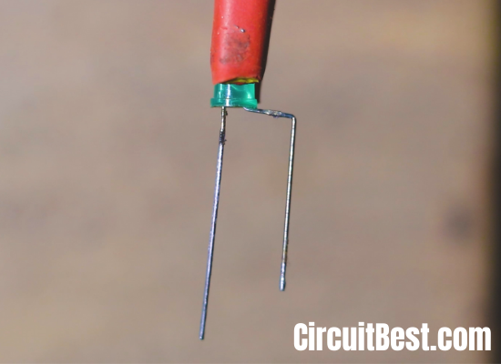
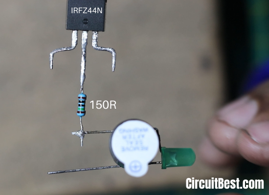
Arrange all Components for the wire break alarm circuit. Place the 5MM LED & Presolder (tin) the LED legs for Better Soldering.
Step 2:
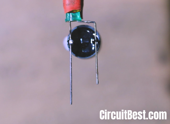
Now take a 5V Buzzer and then connect it with the LED parallelly. Make sure that you are connecting in the right polarity. +ve should be connected with +ve and -ve Should be connected with the -ve. Let’s mark this as Part 1.
Step 3:
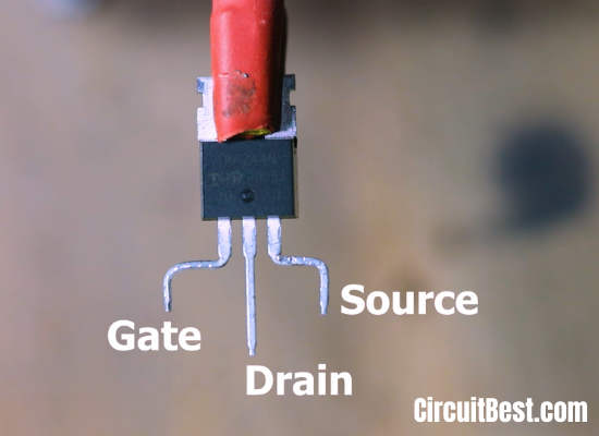
Place the IRFZ44N MOSFET and Presolder (tin) the legs for better soldering. The 3 Pins from Left to Right are Gate, Drain, Source.
Step 4:
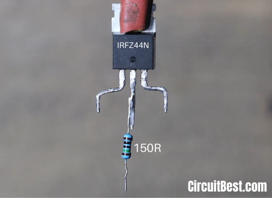
Connect the 150 Ohm resistor with the Drain Pin of the IRFZ44N Mosfet. If you don’t have the value resistor (150 Ohm) then You can use any value between 100Ω to 300Ω Resistor.
Step 5:
Now Let’s Connect Part 1 Circuit -ve with the other pin of the 150-ohm resistor.
Step 6:
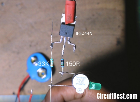
Now connect 33k Resistor with the circuit. Connect one end of 33k resistor with IRFZ44N MOSFET’s Gate Pin. and connect the other end the +ve of the Part 1 Circuit.
Step 7:
Now connect the 9v Battery Clip wires with the circuit. Connect the +ve wire of the 9v Battery clip with the +ve of the Part 1 Circuit. At next Connect the -ve of the 9v Battery clip will be connected with the Source Pin of the IRFZ44N MOSFET.
Step 8:
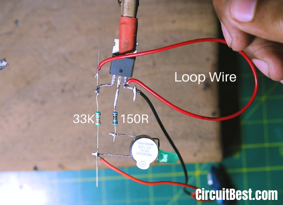
Now connect the Loop wire with the MOSFET’s GATE & SOURCE Pin. This loop wire is the sensor wire. If we cut the Loop wire the Buzzer, as well as the LED, will be ON.
Step 9:
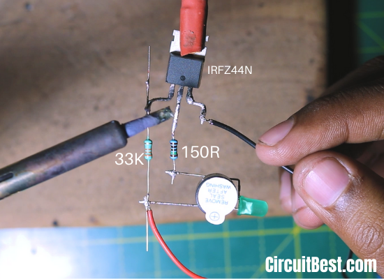
Now you will need a Nose Pliers for cutting the Loop wire. In this way, the wire break circuit works.

Step 10:
Now cut the wire and check that the LED and the Buzzer are on. So, this is the application of wire break alarm circuit.

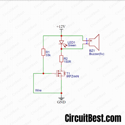
Circuit Schematics:
Here is the Circuit Schematics of the simple wire cut alarm/ Wire Break Alarm. This Buzzer is an Active Buzzer. Here I have used 5V Buzzer. Make sure that you are using the correct parts for the project. for the R1 resistor, you can use any resistor value between 30K to 50K value it will work perfectly fine. For the R2 I have used a 150Ω resistor. R2 is a current limiting resistor. For the R2 you can use any value between 100Ω to 300Ω.
Notes:
1. You should connect all the components in its right polarity.
2. Please add a current limiting resistor with the LED and the BUZZER. Otherwise, it will fuse.
3. You can power the circuit between 9v to 12v. A 9v battery is a very easy solution for wire break alarm circuit.
4. Here we are using an N-Channel Enhancement type MOSFET. So, the load output from the Transistor is high. You can give as high as 6A Load. To it.
5. There is also another way of it. You can connect a relay with the MOSFET. Now the relay will drive external high loads. This is a pretty easy circuit for operating high voltage circuits.
6. You can connect 12V LED Strips, 12v Lamps, 12V Motors and other 12v components with the wire break alarm circuit.
Conclusion:
All in all, we can say that there is so many Application of wire break alarm circuit. You can make a Home safety protection circuit with this cut wire alarm circuit. The components are so cheap and can be found from Utsource and also in local shops. The same type of security protection can be arranged with Microcontrollers Such as Arduino, Raspberry Pi, PIC ICs, and many other controllers. But those are not cheap. So, this is a simple wire break alarm circuit with minimal components.