
Introduction:
Today we will discuss how you can make a Simple Delay Timer Circuit. the way the circuit works is that when you press the push_Button from then the load which is connected with the circuit will work. And after some time the load will off. This is the circuit in a nutshell.
Components Lists From Utsource:
- IRFZ44N: https://www.utsource.net/itm/p/9223667.html
- LED: https://www.utsource.net/itm/p/6831354.html
- Resistor: https://www.utsource.net/itm/p/8328095.html
- Capacitor: https://www.utsource.net/itm/p/1898386.html
Tools Needed:
- Soldering Iron: https://www.utsource.net/itm/p/8423764.html
- Iron Stand: https://www.utsource.net/itm/p/7722853.html
- Nose Pliers: https://www.utsource.net/itm/p/7671655.html
- Flux: https://www.utsource.net/itm/p/8423764.html
How The Circuit Works?
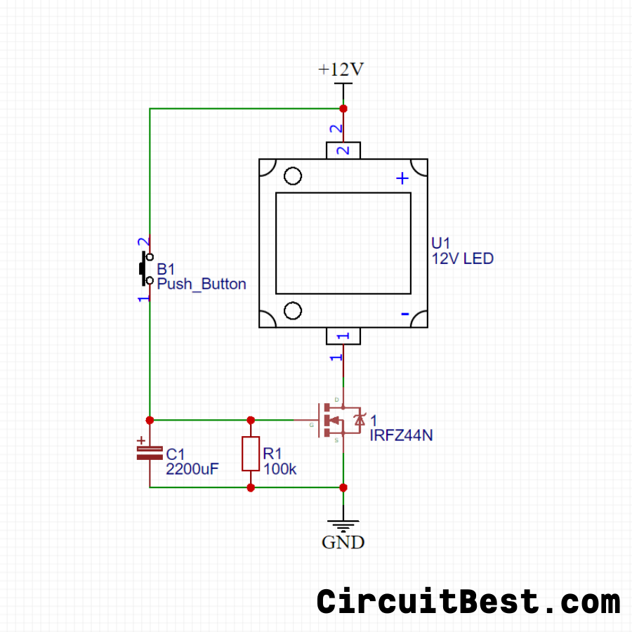
The Delay Timer Circuit is connected with a 12V Power supply.
When you press the Push Button of the Delay Timer then Current flows from Vcc to GND through c1 Capacitor. For this, the Capacitor charges.
Now when we unpress the Button then the Capacitor Discharges through the Mosfet’s GATE Pin. So for this, the MOSFET became conductive. As a result, Current flows from DRAIN to SOURCE Pin.
As a result, the Load which is connected with the circuit will be Powered. In our case, We have Connected a 100w LED.
If you notice the circuit carefully then you can see that we have connected a 100K Resistor parallel with the capacitor. The Resistor is for increasing the Discharge rate for the Capacitor. if you use a higher value resistor then the discharge rate will be low and if you use a lower value resistor then the capacitor discharge rate will be higher for Delay Timer.
In this way the On Delay Timer Circuit Works.
Circuit Diagram:
Here is the Circuit Diagram for the pulse delay circuit
Watch Video:
Here is the Video from Creative creator for a delay timer switch. Watch the video till the end to understand how the circuit works.
Steps For Making the Circuit:
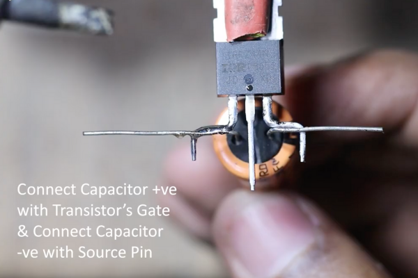
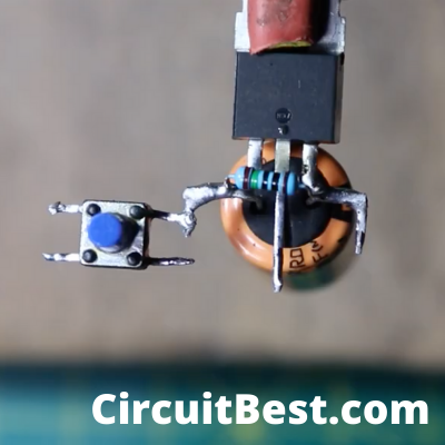
Step 1:
Connect a 2200UF, 25V capacitor with the MOSFET.
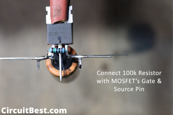
Step 2:
Now, Connect 100k Resistor with IRFZ44N.
Step 3:
Connect Push Button with the Gate of IRFZ44N.
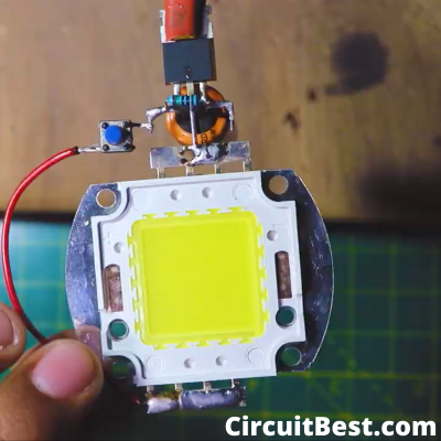
Step 4:
Connect 100W LED -ve with MOSFET’s Drain Pin. And connect LED +ve with Push Button’s other Terminal.
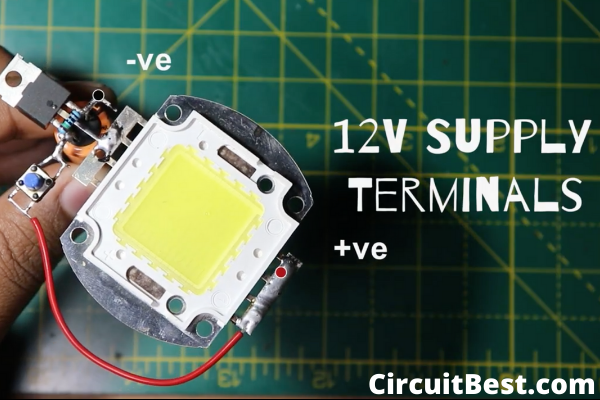
Step 5:
These are the supply Terminals.
Things you Need to Know About off delay timer circuit?
This is a Simple Transistor circuit with some other complementary components. Here we are using an N-Channel Enhancement type Mosfet. as a result, the current output is much higher than a regular NPN Transistor. You can use any other N-Channel Mosfet as you wish. IRFZ44n is a very common MOSFET so in this project, I am Using IRFZ44N Mosfet.
Here the Resistor and the Capacitor are connected in Parallel. The Capacitor charges from the 12V Power supply and the Resistor discharges the capacitor. if you use higher values of resistor then the capacitor will discharge slowly. and if you use a lower value Resistor then the capacitor will discharge very fast and the Delay Timer Circuit will off Very Fast.
In another way, it can happen. Suppose you are choosing a standard value Resistor and then you are varying the Capacitor. If you use a higher value capacitor with respect to the same resistor then the capacitor will take much time to discharge. Now we know the rule for Delay Timer Circuit that if we use a lower value capacitor with respect to the same Resistor then the discharge will be faster compared to the first time.
So my point is that the Delay timer Circuit can be varied with the Resistor and the Capacitor Value.
You can also attach a relay with the Load section of the Mosfet. Now the circuit is off delay timer relay circuit.
You should not choose too much lower value resistor otherwise the discharge rate will be too fast.