When it comes simple Chaser circuit the main thing that comes to our mind is that CD4017 IC. (Not going to microcontroller stuff in this article.) Basically, a CD4017 IC can be configured to run/ Blink 10 LEDs simSchematisultaneously.
The CD4017 IC needs a clock signal to run. In this case we have to mainly use a NE555 Timer IC for the Clock signal generation.
How the Simple LED Chaser circuit with CD4017 works?
The CD4017 is a decoder IC it. takes a single input and converts it to different outputs. In this case it makes 10 different output. This 10 Different outputs can be used to run any external loads such as LEDs.
Here, the 555 Timer provides the PWM Pulses for running the 4017 IC. We can adjust the PWM Pulses by rotating the potentiometer. So, this will increase or decrease the PWM Pulses.
Now, these increasing or decreasing pulses turn the CD4017 to chase the connected load such as LED faster or slower.
Of course, you can connect any bigger high power transistor for running bigger loads. but in this article, I want to keep everything minimal. So, I am using LEDs for testing.
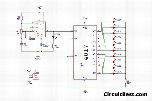
Schematics:
Here is the Schematics for the Project.
Youtube Video:
Why you should make the PCB for the led chaser circuit with CD4017?
Basically, the PCBs are mainly for prototyping. But for big enough projects it is not practical to use breadboards.
If you do a bit of soldering work then you would know that big projects took a lot of solder. If you are using prefboards then it would take even more smoke coming from the soldering iron. The solder had Lead components inside it. This lead is very dangerous for our health.
So, here we will use Printed Circuit Boards. These are nowadays extremely cheap and you get your design ready and got manufactured in a couple of bucks. Later I will discuss that.
If we see the Printed Circuit Boards carefully then you will find that all the solder pads pre-tinned already. So, you just have to add the components and do the remaining soldering process. I think this will be very easy for all.
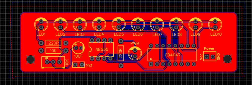
PCB File Creation:
First, we have to create the schematics. I have created the schematics in Easy EDA. and after that, I have converted the schematics to PCB by the given option. Then I arranged all the components in a systematic manner.
Previously we mainly use single Layer PCBs. But this is not that efficient way of making the PCB. PCBs nowadays are mostly 2 layers or more. 2 Layers means Top Layer and Bottom Layer.
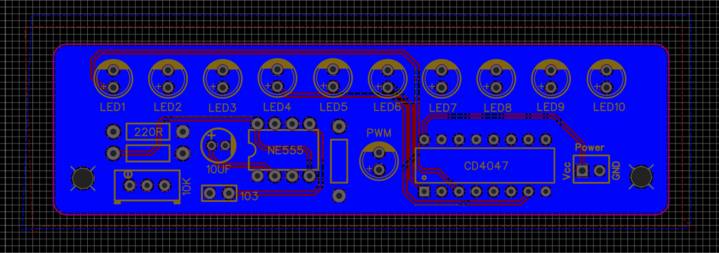
When you are designing a PCB then you will find some times you will run out of space for the tracks. So, in this case, you can switch the layer to a different layer and connect the remaining tracks.
Here the Point is we have to place all the components in such a way that all components connection track would have to be short. this will make the connections more solid and sturdy.
Now I will connect all the tracks with the given tracking tool. Now we are good to go for the next step that is PCB Fabrication.
PCB Order:
Ordering PCB is very simple. You will just need to have your Gerber file of the PCB. This file will be used for ordering the PCB from the PCB manufacturers. Especially for this article, we are using PCBWAY service for making the Project.
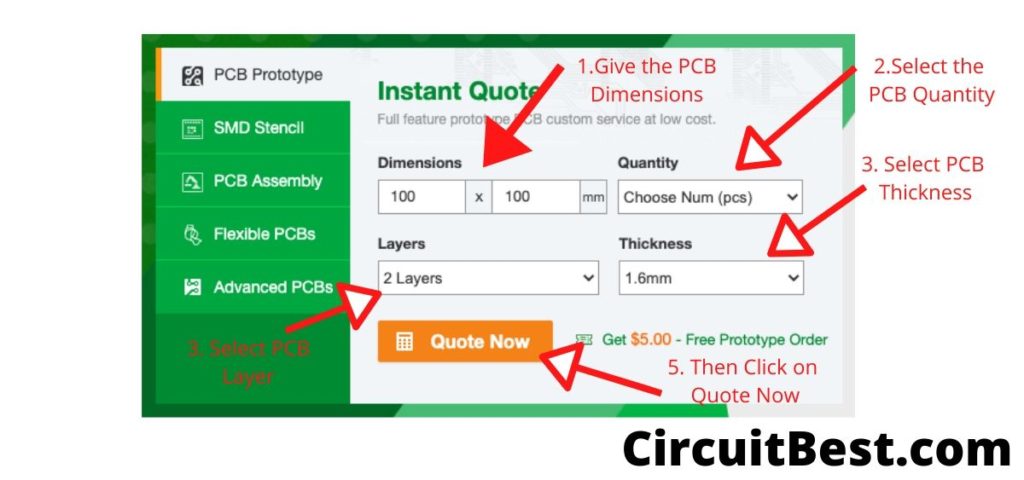
Just open PCB Way select quote not set your PCB dimensions and then upload the Gerber file select PCB settings, Colors and place your order. They are very professional when we would talk about PCB Manufacturing.
Gerber File:
Here is the PCB Gerber file for ordering PCB for this Project.
Conclusion:
All in all, this is a small led chaser circuit with CD4017 IC. That you can build in your home for fun. There is no rocket science involved in this. Also one more time big shout out to PCBWay for Sponsoring. You should definitely try out their PCB Service if you don’t want to compromise any quality. You can also read another article about Arduino Projects.