


Introduction:
Today in this article we are going to make a LED Flasher circuit with a Relay. This is a simple circuit based upon a Multi-Color LED and a General NPN Transistor. So, Let’s make this simple circuit.
0 Profit selling KN95 masks and Infrared Thermometer from UTSOURCE.net: https://www.utsource.net/home/healthcare
Components Lists From Utsource:
- BC547 Transistor: https://www.utsource.net/itm/p/382309.html
- LED: https://www.utsource.net/itm/p/6831354.html
- Resistor: https://www.utsource.net/itm/p/8328095.html
- Capacitor: https://www.utsource.net/itm/p/1898386.html
- Relay: https://www.utsource.net/itm/p/9510225.html
Tools Needed:
- Soldering Iron: https://www.utsource.net/itm/p/8423764.html
- Iron Stand: https://www.utsource.net/itm/p/7722853.html
- Nose Pliers: https://www.utsource.net/itm/p/7671655.html
- Flux: https://www.utsource.net/itm/p/8423764.html
Watch Video:
Here is the video from the Creative Creator YouTube channel. Watch the video and you will understand everything.

Schematics of the LED Flasher Circuit with Relay:

How does the circuit work?
Here we are giving 3v to 5v to the circuit. The Multi-Color LED is connected with the base of the Transistor. The LED changes its color. So, for this reason, the Transistor triggers and the relay turns On/ Off while changing the color. For this triggering, the Relay also triggers.
As a result, the load which is connected with the Relay also triggered. For the Load, I have used 2 LEDs. One of the LED is connected with the NO Pin and the other pin is connected with the NC Pins. Here NO means Normally Opened and the NC means Normally Closed Terminals.
Here you can also connect any load with it. It is a relay so it can handle much higher loads than Transistors. Like you can control 100W Lights easily. So, this is an Easy and Power efficient way of Flashing LED.
Steps for making the Circuit:
Step 1:
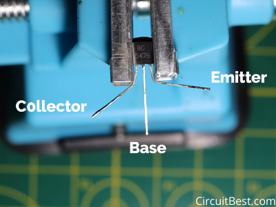
At first Pre-Tin the Legs of the Transistor with a soldering Iron. And also here are the pinouts of the BC547 Transistor. You can also read our other BC547 Projects.
Step 2:
Here I am using 6V relay. The relay can also be operated with 5V. Here are the pinouts of the 6V relay. There are 2 Coil Pins and 3 Contact Terminal Pins. One is common and the other 2 are NO & NC. The NO & NC stands for Normally Opened and Normally closed respectively.

Step 3:
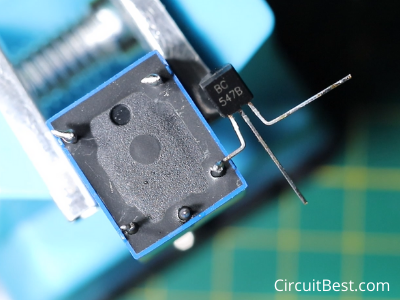
No more Introduction. So, Let’s connect all the components together. First, Connect the Collector pin of the BC547 Transistor with the Relay coil Pin.
Step 4:
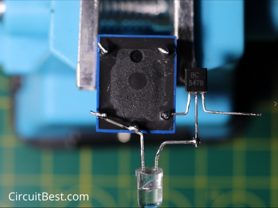
Now take a Multicolor LED and then connect it with the circuit. More precisely connect the LED +ve with the other Relay terminal and connect the -ve of the LED with the Transistor’s Base.
Step 5:
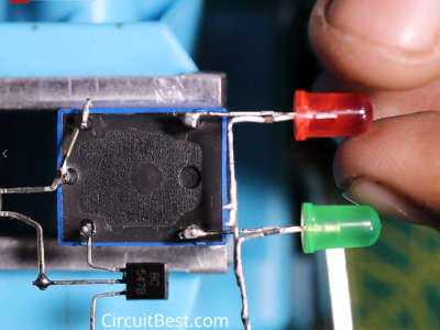
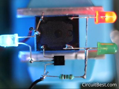
Now take One RED LED and one Green LED. Bend the two LED’s -ve with each other. Now connect the +ve’s of the LED with the NO & NC Pin Respectively as shown in the picture. Make sure that you rate connecting in right polarity otherwise the LEW will not run.
Step 6:
Now connect a 220R resistor with the LED -ve and the Transistor’s Emitter Pin as shown in the picture. Here you have to give 3V to 5V supply. In my case, I have used a 3.7v 18650 LI-Ion Battery. Here you can see the LED is Flashing.
Note:
The circuit is based upon Relay. The Relay is a mechanical device it works but there is a significant noise that comes from it. So, you should take care of these types of things.
Flashing is done by the Multi-color LED. so if the LED is damaged then the circuit will not work. Please don’t use a voltage higher than 5V. otherwise, the Multicolor LED will be damaged and the Relay coil may be heating up quickly.
You can also read our other article about Arduino LED Chaser Circuit Here.


")
