


Introduction:
Today in this article we are going to discuss the dc LED dimmer with IRFZ44N MOSFET. We are using very minimal components in the Circuit Diagram. Just an IRFZ44N N-Channel Mosfet and a Potentiometer. The IRFZ44N is an N-Channel Enhancement type MOSFET to it can Deliver high Output for a simple led dimmer. This Circuit also works with other N-Channel Mosfets as well. That is Pretty much it and you can use the Circuit for LED Dimming. I will thank Utsource for sponsoring.
Components Lists From Utsource:
- IRFZ44N: Link1
- LED Strip: Link1
- 250k Potentiometer: Link1
- 9v Battery: Link1
- 9V Battery Clip: Link1
- Resistor: Link1
Devices Required for LED Strip Dimmer:
Watch Video for led bulb dimmer circuit:
Watch the YouTube video from the Creative Creator for more detailed instructions. You can see step by step process for making the dc dimmer.

Schematics of the Circuit:
How does the 12v Strip Dimmer Circuit Works?
- This is a simple led dimmer that has only 2 components. One is an N-Channel Mosfet and a Potentiometer.
- The Potentiometer is connected with the MOSFET’s GATE Pin. Now rotate the potentiometer. This will adjust the Gate Voltage.
- For the Gate Voltage, The Drain to the source voltage will change. As a result, the voltage will vary according to the Potentiometer Rotation.
In this way, the led dimmer circuit with potentiometer will work.
Schematics for Strip Dimmer Circuit:

Construction and testing for LED Strip Dimmer Circuit:
Step 1:
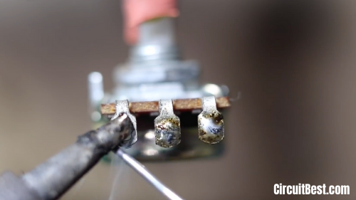
At first, you will need one 250k Potentiometer. This Potentiometer will be used for varying the voltage for dc dimmer circuit.

Step 2:
Place the potentiometer in a certain place. and tin the 3 Points of the Potentiometer for better soldering for LED Dimmer. It will increase the soldering strength.
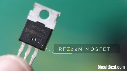
Step3:
Here we are using IRFZ44N MOSFET. The IRFZ44N is an N-Channel Enhancement type MOSFET to it can Deliver high Output for a simple led dimmer circuit. This Circuit also works with other N-Channel Mosfets as well. That is Pretty much it and you can use the Circuit for LED Dimming.
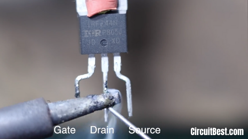
Step 4:
Place the IRFZ44N is an N-Channel Enhancement type MOSFET in a certain place. and tin the 3 Points of the IRFZ44N for better soldering. It will increase the soldering strength for DC BULB Dimmer Circuit.
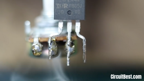
Step 5:
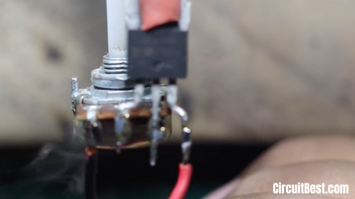
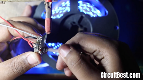
Now connect the Potentiometer and the IRFZ44N with each other like as shown in the picture. The MOSFET’s Gate pin will be connected with the middle pin of the Potentiometer. and connect the drain pin with the corner pin of the Potentiometer.
Step 6:
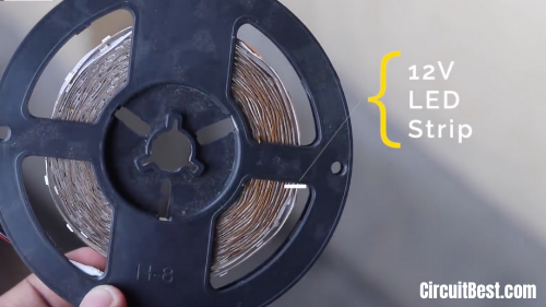
Here we are using a single color 12V LED strip for pwm LED strip dimmer.
Step 7:
Connect the LED Strip +ve wire with the Source Pin of the IRFZ44N Mosfet. and the -ve Pin will be connected with the Potentiometer first Pin.
Step 8:
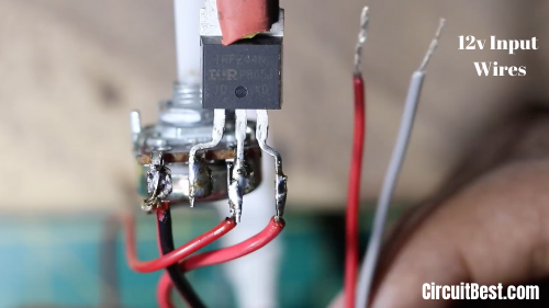
This Red and the Gray wire is for +ve and -ve respectively. We have to give at least 12v for running this board. in this way the Dimmer Circuit works.
Step 9:
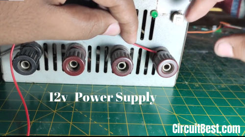
Here I am using a 12V switched-mode power supply (SMPS) for giving the 12v power to the strip Dimmer Circuit.
Step 10:
Now everything is pretty much done. If you rotate the potentiometer then you will see that bulb dimmer circuit function is working fine.
Conclusion:
All in all, we can say that there is so many Application of LED Strip Dimmer. You can make 100W Dimmer circuit, Motor Speed Controller with this board. The components are so cheap and can be found from Utsource and also in local shops. The same type of security protection can be arranged with Microcontrollers Such as Arduino, Raspberry Pi, PIC ICs, and many other controllers. But those are not cheap. So, this is a simple led dimmer with minimal components.
You can also read another article about Wire Break Alarm Circuit


")
